Radio-frequency front-end circuit and communication device
a radio-frequency front-end and communication device technology, applied in the direction of electrical equipment, transmission, impedence networks, etc., can solve the problems of difficult to respond to a request for miniaturization of radio-frequency front-end modules, filter characteristics deterioration, etc., to achieve low loss, reduce production costs, and simplify the effect of manufacturing process and miniaturization
- Summary
- Abstract
- Description
- Claims
- Application Information
AI Technical Summary
Benefits of technology
Problems solved by technology
Method used
Image
Examples
first preferred embodiment
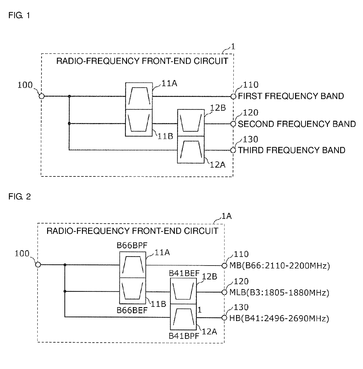
[0100]FIG. 1 is a circuit configuration diagram of a radio-frequency front-end circuit 1 according to a first preferred embodiment of the present invention. As shown in FIG. 1, the radio-frequency front-end circuit 1 preferably includes a first filter 11A, a first band elimination filter 11B, a second filter 12A, a second band elimination filter 12B, an antenna common terminal 100, and input-output terminals 110, 120, 130. The radio-frequency front-end circuit 1 is a multiplexer-demultiplexer circuit including the first filter 11A, the second filter 12A, and the pair of first band elimination filter 11B and second band elimination filter 12B. The first filter 11A, the second filter 12A, and the pair of first band elimination filter 11B and second band elimination filter 12B are bound by the antenna common terminal 100.
[0101]The antenna common terminal 100 is preferably connectable to, for example, an antenna element. Each of the input-output terminals 110, 120, 130 is connectable to...
second preferred embodiment
[0173]In the present preferred embodiment, a radio-frequency front-end circuit 1B applied to an LTE multiband system different from the system to which the radio-frequency front-end circuit 1A according to the first preferred embodiment is applied, and a communication device on which the radio-frequency front-end circuit 1B is mounted will be described.
[0174]FIG. 7 is a specific circuit configuration diagram of the radio-frequency front-end circuit 1B according to the second preferred embodiment of the present invention. The radio-frequency front-end circuit 1B shown in FIG. 7 preferably includes the first filter 11A, a first band elimination filter 11C, the second filter 12A, a second band elimination filter 12C, the antenna common terminal 100, and the input-output terminals 110, 120, 130. The radio-frequency front-end circuit 1B is a multiplexer-demultiplexer circuit including the first filter 11A, the second filter 12A, and the pair of first band elimination filter 11C and secon...
third preferred embodiment
[0187]In the present preferred embodiment, a radio-frequency front-end circuit 1C applied to an LTE multiband system different from the system to which the radio-frequency front-end circuit 1A according to the first preferred embodiment is applied or the system to which the radio-frequency front-end circuit 1B according to the second preferred embodiment is applied will be described.
[0188]FIG. 9 is a specific circuit configuration diagram of the radio-frequency front-end circuit 1C according to the third preferred embodiment. The radio-frequency front-end circuit 1C shown in FIG. 9 preferably includes the first filter 11A, a first band elimination filter 11D, the second filter 12A, a second band elimination filter 12D, the antenna common terminal 100, and the input-output terminals 110, 120, 130. The radio-frequency front-end circuit 1C is preferably a multiplexer-demultiplexer circuit including the first filter 11A, the second filter 12A, and the pair of first band elimination filt...
PUM
 Abstract
Description
Claims
Application Information
 - R&D
- Intellectual Property
- Life Sciences
- Materials
- Tech Scout
- Unparalleled Data Quality
- Higher Quality Content
- 60% Fewer Hallucinations
Browse by: Latest US Patents, China's latest patents, Technical Efficacy Thesaurus, Application Domain, Technology Topic, Popular Technical Reports.
© 2025 PatSnap. All rights reserved.Legal|Privacy policy|Modern Slavery Act Transparency Statement|Sitemap|About US| Contact US: help@patsnap.com


