Perpendicular magnetic write head

a write head and perpendicular technology, applied in the field of perpendicular magnetic write head, can solve the problems of insufficient recording (writing) capability, insufficient volume of magnetic pole tip portion, and residual flux becoming likely to leak out of magnetic pole layer, so as to suppress the unintended erasure of information at the time of non-writing

Inactive Publication Date: 2011-03-17
SAE MAGNETICS (HK) LTD
View PDF11 Cites 0 Cited by
  • Summary
  • Abstract
  • Description
  • Claims
  • Application Information

AI Technical Summary

Benefits of technology

[0012]According to the perpendicular magnetic write head, since the magnetic pole tip portion and the first yoke portion are integrally formed with the vapor deposition method and the second yoke portion is formed with the plating method, the magnetic flux intake capacity of the magnetic pole tip portion is ensured, and residual flux becomes less likely to leak out of the magnetic pole tip portion at the time of writing. Therefore, unintended erasure of information at the time of non-writing can be suppressed while keeping the capability of writing.

Problems solved by technology

As a result, the volume (magnetic flux intake capacity) of the magnetic pole tip portion is decreasing, and thus the recording (writing) capability tends to be insufficient.
Moreover, residual flux becomes likely to leak out of the magnetic pole layer due to the magnetic domain structure of the yoke portion, which occupies a most port of the magnetic pole layer.
As a result, unintended erasure of information written on the recording medium may occur at the time of non-writing.

Method used


Image

  • Perpendicular magnetic write head
  • Perpendicular magnetic write head
  • Perpendicular magnetic write head

Examples


Embodiment Construction

[0023]An embodiment of the invention will be described in detail hereinbelow with reference to the drawings.

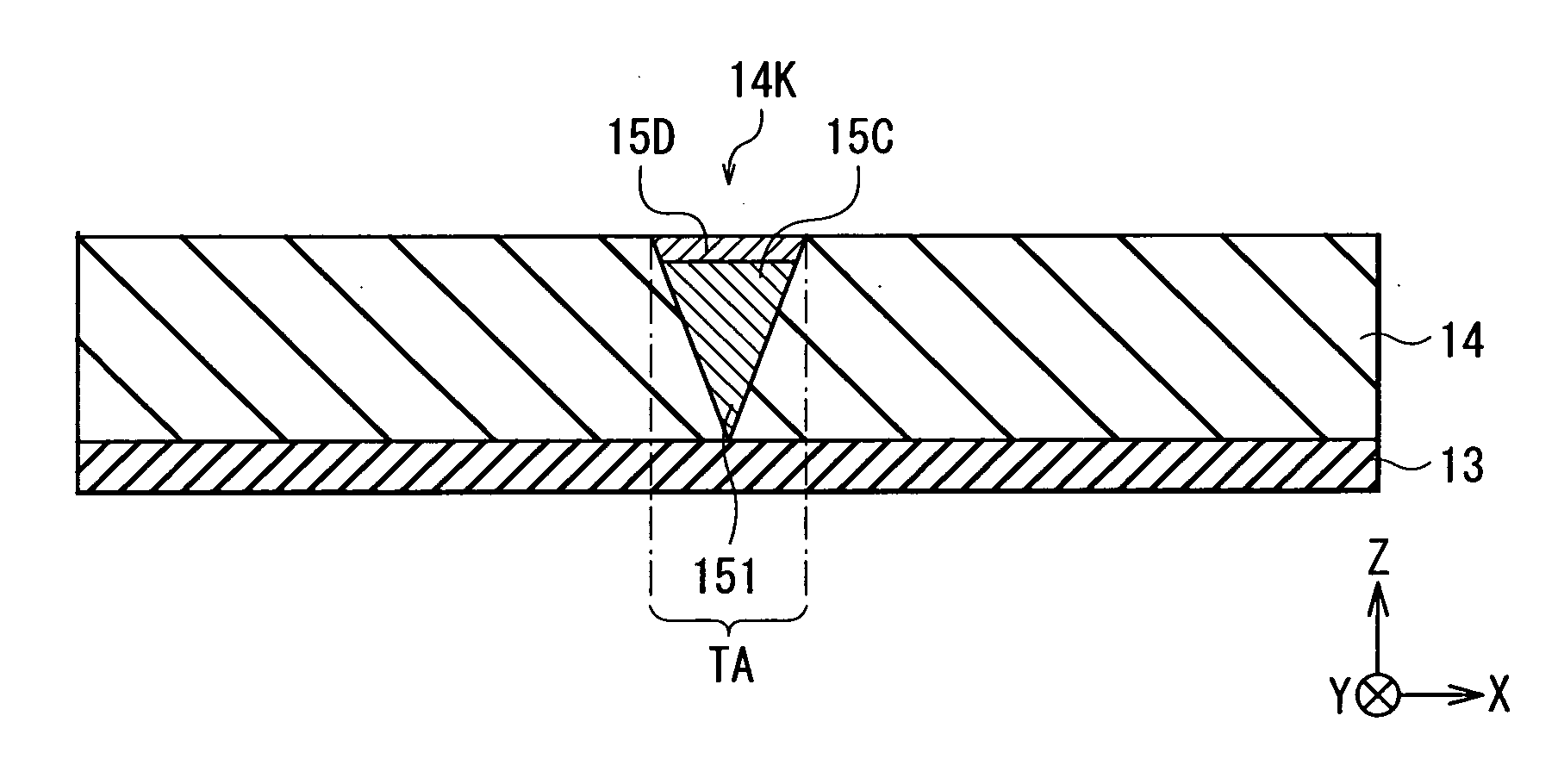
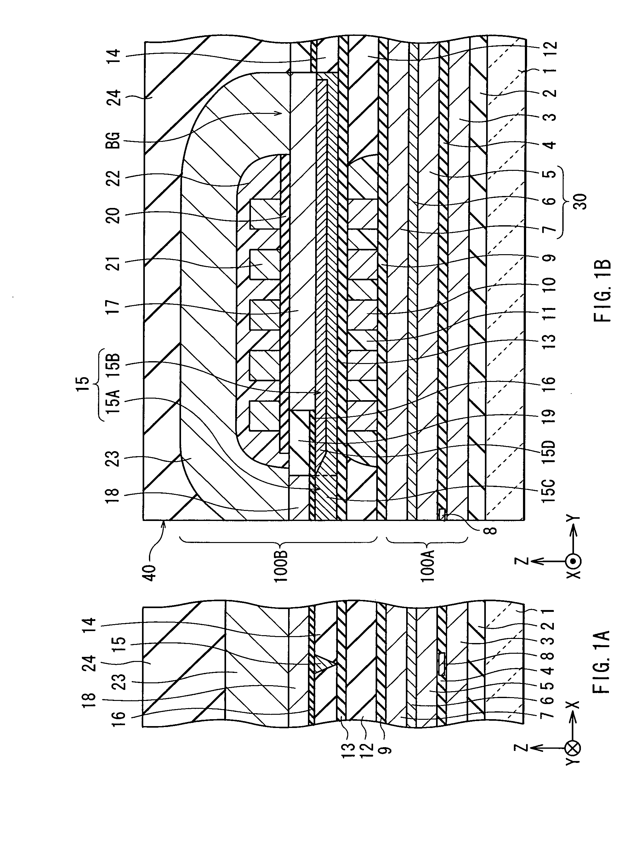
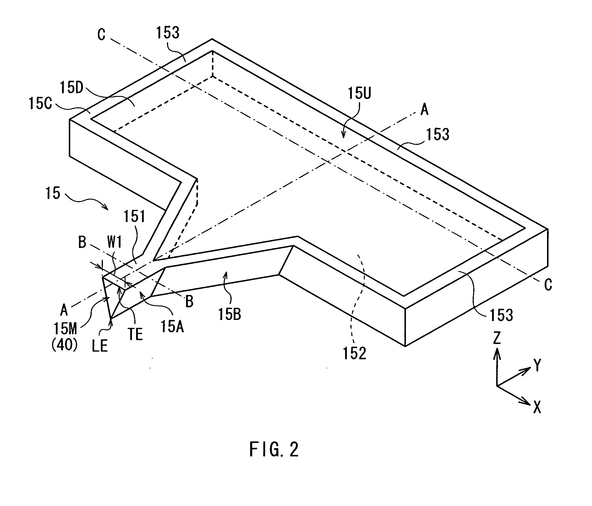
[0024]First, explanation will be made on a configuration of a thin film magnetic head provided with a perpendicular magnetic write head according to an embodiment of the present invention. FIG. 1A and FIG. 1B show a cross-sectional configuration of the thin film magnetic head respectively parallel to and perpendicular to an air bearing surface 40.

[0025]In the following description, dimensions in X-axis, Y-axis, and Z-axis directions represented in FIG. 1A and FIG. 1B are defined as “width”, “length” and “thickness” respectively. In addition, a side closer to the air bearing surface 40 in the Y-axis direction is defined as a “front side” and a side far therefrom is defined as a “rear side”. Further, if a state of a recording medium (not shown) which makes a relative movement with respect to the thin film magnetic head is regarded as a stream, a side ahead of (upper side of) the...


PUM

PropertyMeasurementUnit
widthaaaaaaaaaa
surface writing densityaaaaaaaaaa
magnetic fieldaaaaaaaaaa

Abstract

A perpendicular magnetic write head in which unintended erasure of information at the time of non-writing can be suppressed while keeping the capability of writing is provided. The perpendicular magnetic write head includes a magnetic pole tip portion, a first yoke portion connected to the magnetic pole tip portion, having a width larger than that of the magnetic pole tip portion, and having a recess portion in a center region thereof, and a second yoke portion embedded in the recess portion. The magnetic pole tip portion and the first yoke portion are integrally formed with a vapor deposition method, and the second yoke portion is formed with a plating method. Since the saturation flux density of the magnetic pole tip portion formed with the vapor deposition method becomes higher than that of the yoke portion, a magnetic flux intake capacity of the magnetic pole tip portion is ensured. In a magnetic domain structure of the yoke portion most of which is formed with the plating method, since an easy magnetization axis becomes likely to be directed in a direction perpendicular to an emitting direction of a magnetic flux, residual flux becomes less likely to leak out of the main magnetic pole layer at the time of non-writing.

Description

BACKGROUND OF THE INVENTION[0001]1. Field of the Invention[0002]The present invention relates to a perpendicular magnetic write head provided with a magnetic pole layer that includes a magnetic pole tip portion of a narrow width defining a width of a write track and a yoke portion of a large width connected thereto.[0003]2. Description of the Related Art[0004]In recent years, performance improvement of a magnetic write head is required because of the increasing surface writing density of a magnetic recording medium such as a hard disk (hereinafter referred to as “recording medium”). Accordingly, a magnetic write head of a perpendicular magnetic write type (perpendicular magnetic write head) in which a signal magnetic field is set in a direction perpendicular to a recording surface of the recording medium attracts attention. This is because of advantages that a linear recording density becomes high and that the recorded recording medium is less affected by the influence of heat fluct...

Claims


Application Information

Patent Timeline
Patent Type & Authority Applications(United States)
IPC IPC(8): G11B5/187
CPCG11B5/1278G11B5/3163G11B5/3116
Inventor MINO, TETSUYAMATONO, NAOTOONODERA, IKUHITONISHIYAMA, KAZUSHITSUCHIYA, MICHITOSHISASAKI, KENJI
Owner SAE MAGNETICS (HK) LTD
Why Eureka
Try Eureka