Combination sensor guidewire and methods of use

a combined sensor and guidewire technology, applied in the field of ultra-miniaturized combined pressure sensors and flow sensors, can solve the problems of less accurate pressure measurements, inaccurate pressure measurements, and less efficacy of methods, and achieve the effects of minimizing the effect of side branch theft, increasing the placement accuracy of sensors, and improving accuracy and consistency in measurements

Active Publication Date: 2006-10-26
VOLCANO CORP
View PDF77 Cites 76 Cited by
  • Summary
  • Abstract
  • Description
  • Claims
  • Application Information

AI Technical Summary

Benefits of technology

[0012] The present invention provides for combination sensor tip which may be secured to the distal end of a guidewire having an ultra miniature pressure sensor and an ultrasound transducer mounted on or near the distal end of the combination sensor housing. In this embodiment, the pressure sensor and the ultrasound transducer are mounted in close proximity to one another in order to enable pressure and flow velocity measurements to be taken at substantially the same time and location, and thus ensure a greater accuracy and consistency in the measurements. For example, the proximity of the pressure and flow sensors minimizes the effect of side branch steal which can cause hemodynamic changes over short segments. The close proximity of the sensors also increases the placement accuracy of the sensors. Finally, the distal placement of the pressure sensor and ultrasound transducer on the combination tip increases how far the sensors may be advanced within the body.
[0013] The present invention also provides for a guidewire with an increased tubular wall thickness and a larger diameter core wire. This embodiment provides improved stiffness in the proximal section of the guidewire, making it more durable and resistant to kinking, while maintaining the ability to insulate the electrical conductors and permitting them to freely extend from the pressure sensor and ultrasound transducer inside the guidewire without damage. In one embodiment, this increased stiffness is achieved by using an elongate tubular member with a thickened wall containing a groove for each electrical conductor extending the length of the tubular member. The electrical conductors may then be positioned in the grooves where they will still have space to freely extend the length of the cable. Since the conductors are resting partially inside the grooves, the thickness of the tubular member walls may be increased without cutting onto the free space for the electrical conductors. In an alternative embodiment, the stiff inner core wire may also be increased in diameter to further reinforce the stiffness of the guidewire. Alternatively, the guidewire may be created out of a composite polyimide tube wherein the electrical conductor wires may be sandwiched between layers of the polyimide tube as it is being formed. In this embodiment, the diameter of the stiff inner core wire may also be increased since the wires are embedded in the polyimide tube and no longer need the space between the tubular member and the inner core wire to freely extend. Furthermore, since the electrical conductors are insulated by the polyimide layers, additional insulating material between the electrical conductors and the steel inner core wire is no longer necessary. Thus, the diameter of the inner core wire may be even further enlarged.
[0014] The present invention also provides for an improved connector to couple a guide wire to a physiology monitor. The connector includes an outer housing having an inner passage which further contains a stationary contact housing for electrically connecting to the conductors of the coupled guidewire and a rotatable bearing assembly for physically engaging the wire. In this embodiment, the bearing assembly of engages the wire and is able to freely spin while the connector housing and the contact housing remain static. This spinning capability of the bearing assembly reduces torsional resistance between the guide wire and a cable or monitor to which it is connected, thereby allowing a user to manipulate the guide wire using less torque than required with current connectors.

Problems solved by technology

Such an approach has, however, been less efficacious as the diameters of the catheters became smaller with the need to advance the catheter into smaller vessels and to the distal side of atherosclerotic lesions.
This made necessary the use of smaller lumens that gave less accurate pressure measurements and in the smallest catheters necessitated the elimination of such a pressure lumen entirely.
Furthermore, the catheter is large enough to significantly interfere with the blood flow and damp the pressure resulting in an inaccurate pressure measurement.
As a result, the current designs do not allow a user to take both Doppler flow measurements using the ultrasound transducer and pressure measurements using the pressure sensor at substantially the same time at the same location, or to take both measurements near the distal tip of the guide wire.
The additional distal movement of the guide wire using the current designs is undesirable as such movement may inflict trauma (or further trauma) to the body, such as, e.g., to the arterial walls.
Another disadvantage of the separated placement of the ultrasound transducer and the pressure sensor on currently proposed designs is that there may be a limit as to how far distally a measurement may be taken with the guide wire.
For example, the currently proposed designs are not able to take a measurement at the extreme distal end of a cavity or body lumen because there is no room to maneuver the pressure sensor distally to the desired location once the distal end of the guide wire is in physical contact with the distal end of the body lumen.
Also, when attempting to advance one sensor to the location at which a measurement was already taken with the other sensor, it is difficult to know the exact location to stop the advancement.
Unfortunately, the current methods for coupling and decoupling the guide wire directly to the physiology monitor or to a cable leading to the physiology monitor are deficient in certain respects.
During connection, there is a substantial risk that the proximal end of the guidewire and / or male connector may be bent and the electrical connections may be damaged.
However, these properties are limited by the need to electrically insulate the electrical conductors and to ensure that the electrical conductors have enough space to freely extend without damage.
The use of five electrical conductors in a combination pressure and flow sensor guidewire, instead of the traditional two or three conductors for stand alone flow or pressure sensor guidewires, further complicates the solution.
Additionally, the use of traditional rotary connectors to connect the guidewire to the physiology monitor may render the guide wire awkward to manipulate and often require high insertion forces to place the guide wire in the connector.
These traditional connectors also exhibit a high degree of torsional resistance, which also increases the difficulty of manipulating the guide wire within the body.

Method used


Image

  • Combination sensor guidewire and methods of use
  • Combination sensor guidewire and methods of use
  • Combination sensor guidewire and methods of use

Examples


Embodiment Construction

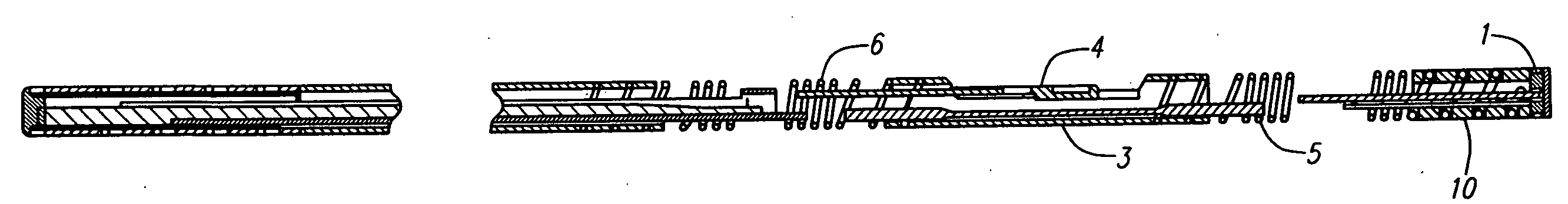
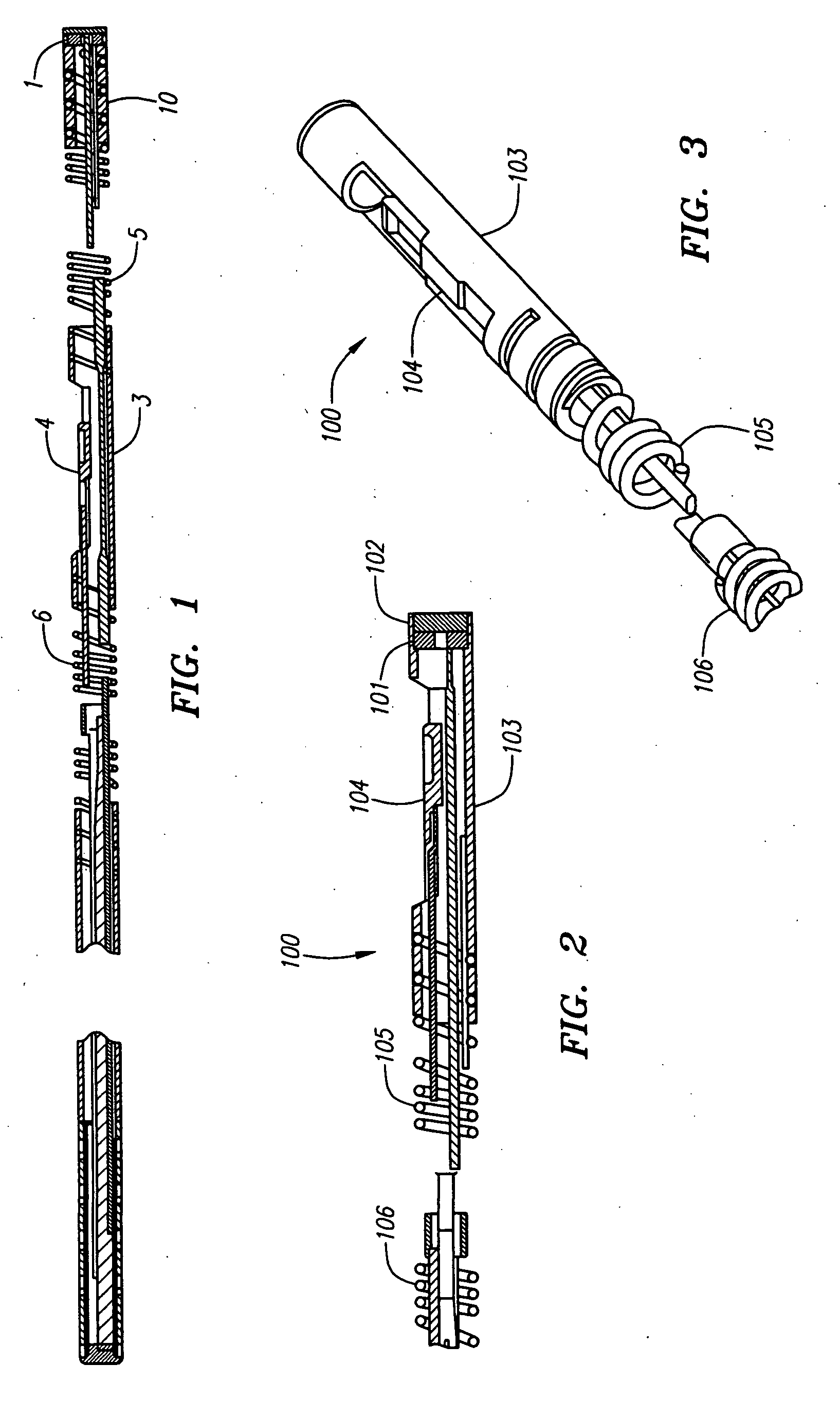
[0044] Turning to FIGS. 2-3, a combination sensor tip 100 of the present invention is illustrated. The combination sensor tip 100 includes a flow sensor 101, for example an ultrasound transducer, a Doppler flow sensor or any other suitable flow sensor, disposed at or in close proximity to the distal end 102 of the combination sensor tip 100. The ultrasound transducer 101 may be any suitable transducer, and may be mounted in the distal end using any conventional method, including the manner described in U.S. Pat. No. 5,125,137, which is fully incorporated herein by reference. Conductors (not shown) may be secured to the front and rear sides of the ultrasound transducer 101, and the conductors may extend interiorly to the proximal extremity of a guide wire.

[0045] The combination sensor tip 100 also includes a pressure sensor 104 also disposed at or in close proximity to the distal end 102 of the combination sensor tip 100. The pressure sensor 104 may be of the type described in U.S. ...


PUM


Abstract

The present invention provides for an improved combination sensor tip that includes a pressure sensor and a second sensor other than a pressure sensor, both disposed at or in close proximity to the distal end of the combination sensor tip. The present invention also provides for an improved connector to couple a guide wire to a physiology monitor that reduces torsional resistance when maneuvering the guide wire.

Description

RELATED APPLICATIONS [0001] This is a continuation of U.S. application Ser. No. 11 / 236,318, filed on Sep. 26, 2005, which claims the benefit of U.S. provisional patent application Ser. No. 60 / 613,847, entitled Improved Connector and Combined Miniature Pressure and Flow Sensor, filed Sep. 27, 2004 which are incorporated herein by reference in their entirety for all purposes.FIELD OF THE INVENTION [0002] This invention relates to an ultra miniature combined pressure sensor and flow sensor, an apparatus using the same, and methods for using the same. This invention also relates to an improved connector for connecting a guide wire to a monitor. This invention is particularly suitable for making pressure measurements in coronary arteries of human beings. BACKGROUND [0003] It has been well known that it is desirable to make pressure measurements in vessels and particularly in coronary arteries with the advent of angioplasty. Typically in the past, such pressure measurements have been made...

Claims


Application Information

Patent Timeline
Patent Type & Authority Applications(United States)
IPC IPC(8): A61B5/02A61M25/00A61B5/00
CPCA61B5/02158A61B8/445A61B8/12A61B8/06A61B5/0215A61B2562/0247
Inventor AHMED, MASOODOLIVER, EDWARD ANTHONYPULEO, JOSEPHINGMAN, CHRISTOPHER DEEWALKER, BLAIR D.
Owner VOLCANO CORP
Why Eureka
Try Eureka