

Sous vide cooker with integrated immersion circulator
a circulator and suv technology, applied in the field of suv cooking, can solve the problems of reducing the cooking temperature of the final product, requiring significantly less salt and oil, and retaining the taste, so as to maintain the setting and heating ability, and reduce heat loss
- Summary
- Abstract
- Description
- Claims
- Application Information
AI Technical Summary
Benefits of technology
Problems solved by technology
Method used
Image

Examples
Embodiment Construction
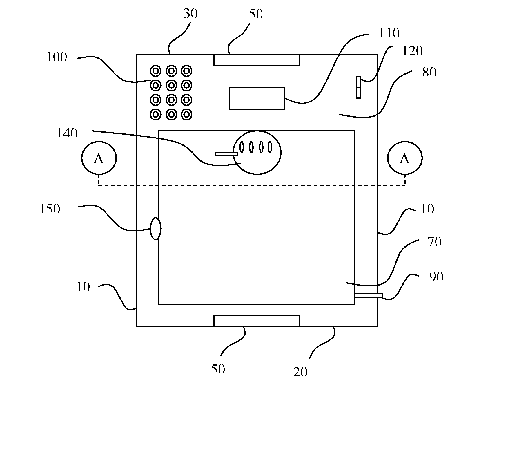
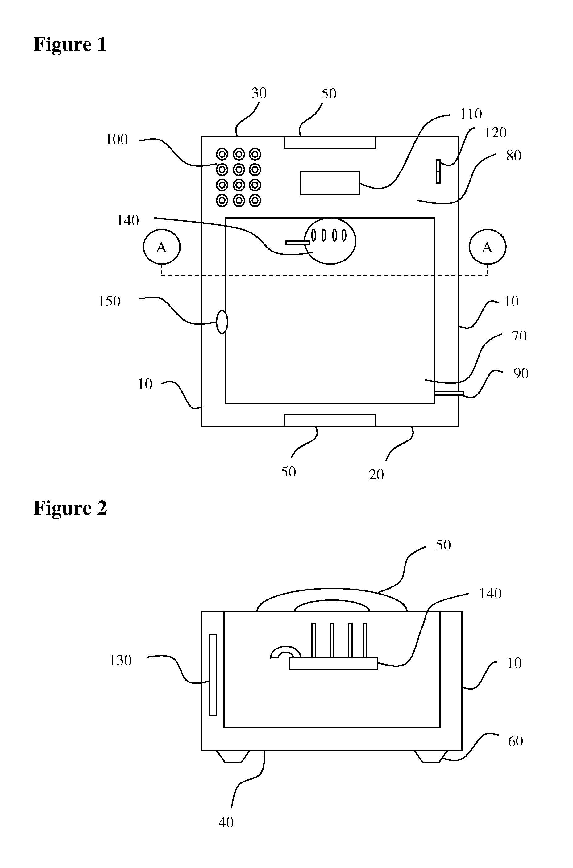
[0016] The method and appliance of the present invention allow for sous vide cooking, suitable for in-home or professional use. In the context of the present invention, users may include individuals or groups of individuals desiring to prepare food using the sous vide cooking method. These users could be professional cooks, such as at a restaurant, café, or cafeteria or could be home users in their personal kitchens.
[0017] One embodiment of the appliance is shown in FIG. 1 and FIG. 2. The appliance includes two side walls 10, a front wall 20, a rear wall 30, and a bottom wall 40. On top of the front and rear walls handles are mounted 50, to allow the appliance to be moved easily and without spilling the contents if full. On the bottom wall rubber footings are attached 60 to provide stability to the appliance and prevent it from inadvertently slipping or moving. On the inside, the appliance is divided into two chambers, a heating chamber 70 and an electronic control chamber 80. The ...
PUM
 Abstract
Description
Claims
Application Information