
Systems and methods for electronic weaponry that detects properties of a unit for deployment

a technology of electronic weaponry and properties, applied in the field of systems and methods for electronic weapons, can solve the problem that the control functions of conventional electronic weapons are not responsive to the status of cartridges

Active Publication Date: 2011-03-17
AXON ENTERPRISE INC
View PDF23 Cites 11 Cited by
  • Summary
  • Abstract
  • Description
  • Claims
  • Application Information

AI Technical Summary

Benefits of technology

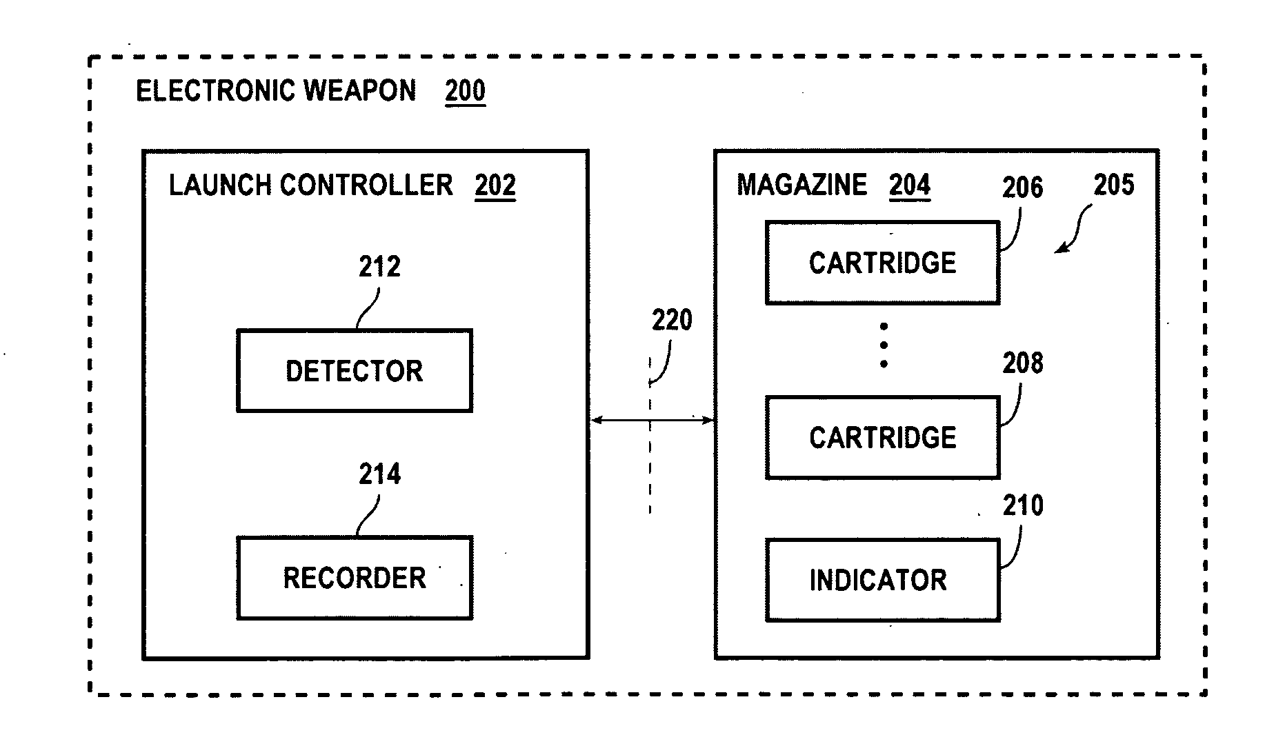
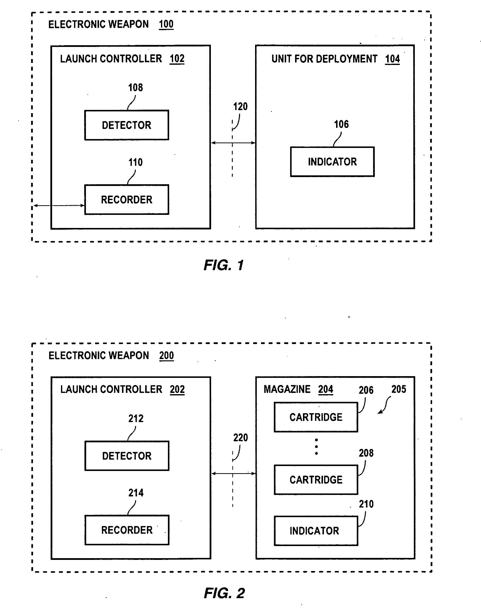
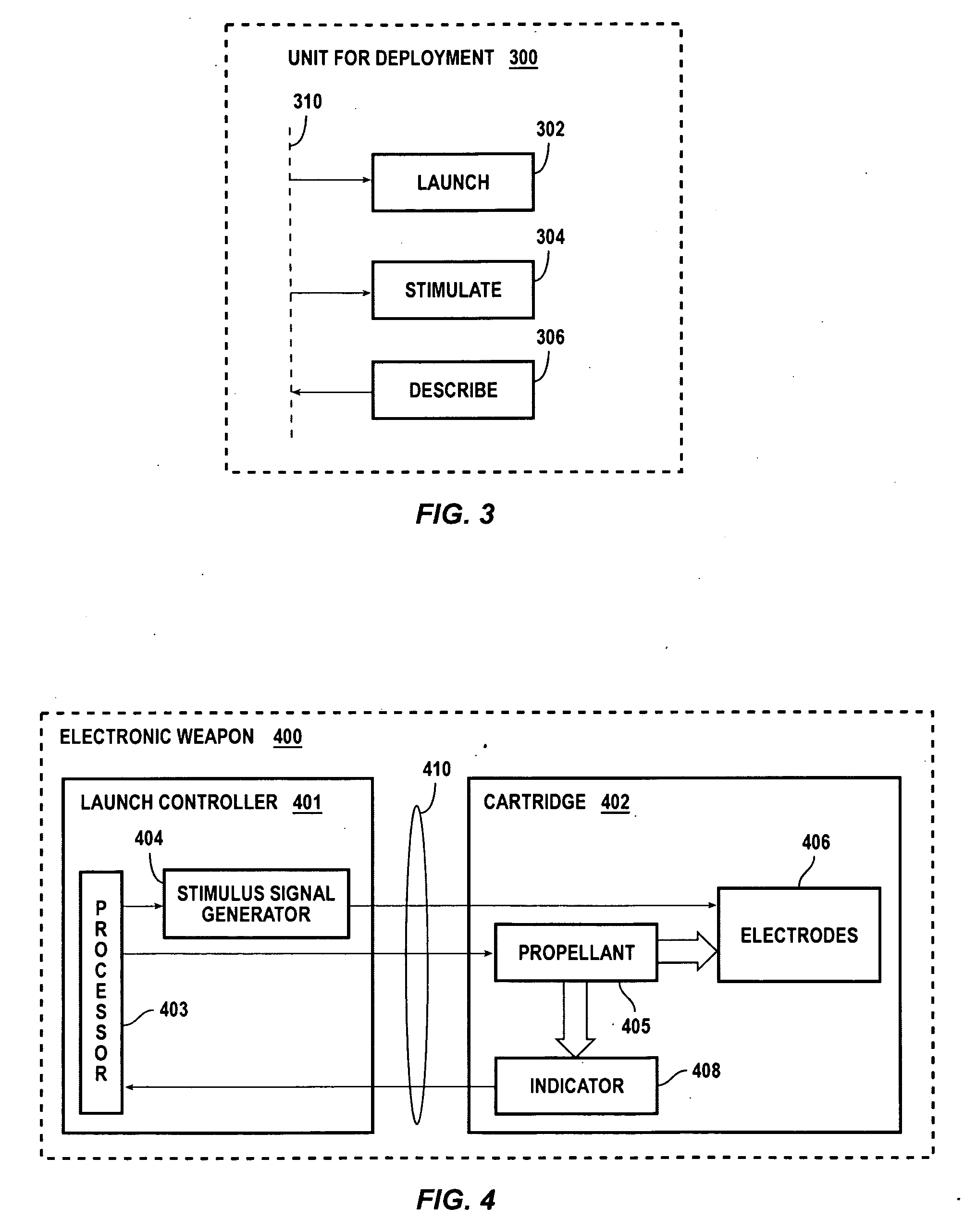
The present invention relates to electronic weaponry and aims to reduce the training required for users and the limitations of conventional electronic weapons. The invention provides a system for deploying electronic weapons with a unit for deployment that can automatically detect the type of cartridge installed and respond accordingly. The invention also includes different types of electronic weapons, such as a handheld weapon, a gun, an installation, a grenade, a mine, or an armed robot, that can all be used with the invention. The invention uses a stimulus signal to interfere with the target's use of its skeletal muscles, causing a temporary stun function. The current is quantified in various ways and can be adjusted to provide a more effective stun signal. The invention also includes a simplified schematic diagram of the interface between the electronic weapon and the target. Overall, the invention improves the training and effectiveness of electronic weapons for interfering with the locomotion of a target.

Problems solved by technology

Further, the control functions of a conventional electronic weapon are not responsive to the status of a cartridge (e.g. ready or already fired).

Method used


Image

  • Systems and methods for electronic weaponry that detects properties of a unit for deployment
  • Systems and methods for electronic weaponry that detects properties of a unit for deployment
  • Systems and methods for electronic weaponry that detects properties of a unit for deployment

Examples


Embodiment Construction

[0015]An individual such as a police officer, a military soldier, or a private citizen may desire to interfere with the voluntary locomotion of a target (e.g., one or more persons or animals). Locomotion by a target may include movement toward and / or away from the individual by all or part of the target. An individual may desire to interfere with locomotion by a target for defensive or offensive purposes (e.g., self defense, protection of others, defense of property, controlling access to an area, threat elimination). For example, terrorists may be stopped in assaults and prevented from completing acts involving force to gain unlawful control of facilities, equipment, operators, innocent citizens, and law enforcement personnel. In another example, law enforcement officers may arrest and maintain the cooperation of persons by using an electronic weapon against that person or persons.

[0016]An electronic weapon includes any weapon that passes a current through a circuit that includes a...


PUM


Abstract

An electronic weapon, when combined with a unit for deployment, causes skeletal muscle contractions in a human or animal target. According to the present invention, a launch controller for an electronic weapon includes a detector, a stimulus signal generator, and a switch. When the switch is conducting, it completes a circuit in combination with a unit for deployment. The circuit, when completed, operates a propellant of the unit for deployment to deploy at least two electrodes of the unit for deployment to enable the stimulus signal generator to deliver through the target a stimulus current to incapacitate the target by causing contractions of the skeletal muscles of the target. The detector is coupled to the switch and detects whether the switch is conducting prior to combining the unit for deployment and the electronic weapon.

Description

FIELD OF THE INVENTION[0001]Embodiments of the present invention relate to systems and methods for electronic weaponry.BACKGROUND OF THE INVENTION[0002]Conventional electronic weapons have an interface to accept a cartridge. When activated by the weapon, the cartridge deploys electrodes toward a target. The spent cartridge is removed manually and replaced with another cartridge for another activation with the same or a different target. Several conventional cartridge types, each type with a different range (e.g., length of wire-tethers for electrodes), have been developed to operate interchangeably with a conventional electronic weapon via this interface. Users of conventional electronic weapons are trained to accommodate several limitations of an electronic weapon. For example, a user must be aware of the type of cartridge presently installed at the interface because the electronic weapon is not aware. Further, the control functions of a conventional electronic weapon are not respo...

Claims


Application Information

Patent Timeline
Patent Type & Authority Applications(United States)
IPC IPC(8): F41B15/04G01R31/02
CPCF41B15/04F41H13/0012
Inventor BRUNDULA, STEVEN N.D.NERHEIM, MAGNE H.CEROVIC, MILAN
Owner AXON ENTERPRISE INC
Learn More