Method and apparatus for transmitting downlink signal in a MIMO wireless communication system

Active Publication Date: 2011-03-17
LG ELECTRONICS INC
View PDF11 Cites 122 Cited by
  • Summary
  • Abstract
  • Description
  • Claims
  • Application Information

AI Technical Summary

Benefits of technology

[0033]A method for efficiently configuring downlink control in

Problems solved by technology

In case of downlink signal transmission that uses a new MIMO scheme different from the existing MIMO scheme, a problem may occur in tha

Method used


Image

  • Method and apparatus for transmitting downlink signal in a MIMO wireless communication system
  • Method and apparatus for transmitting downlink signal in a MIMO wireless communication system
  • Method and apparatus for transmitting downlink signal in a MIMO wireless communication system

Examples


first embodiment

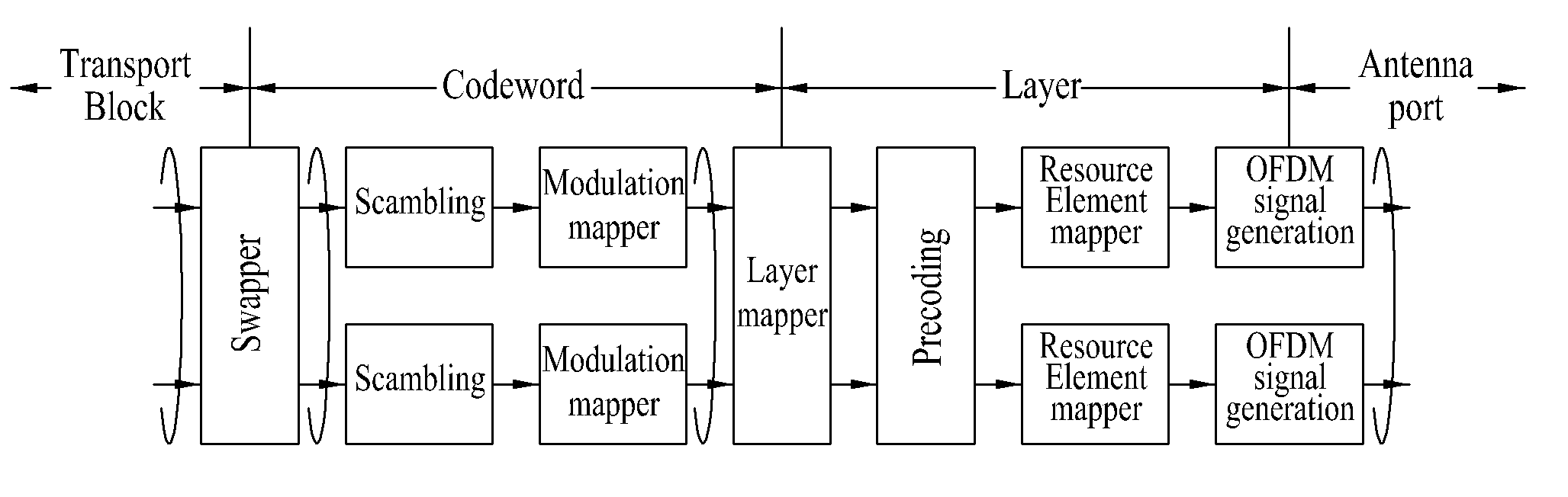
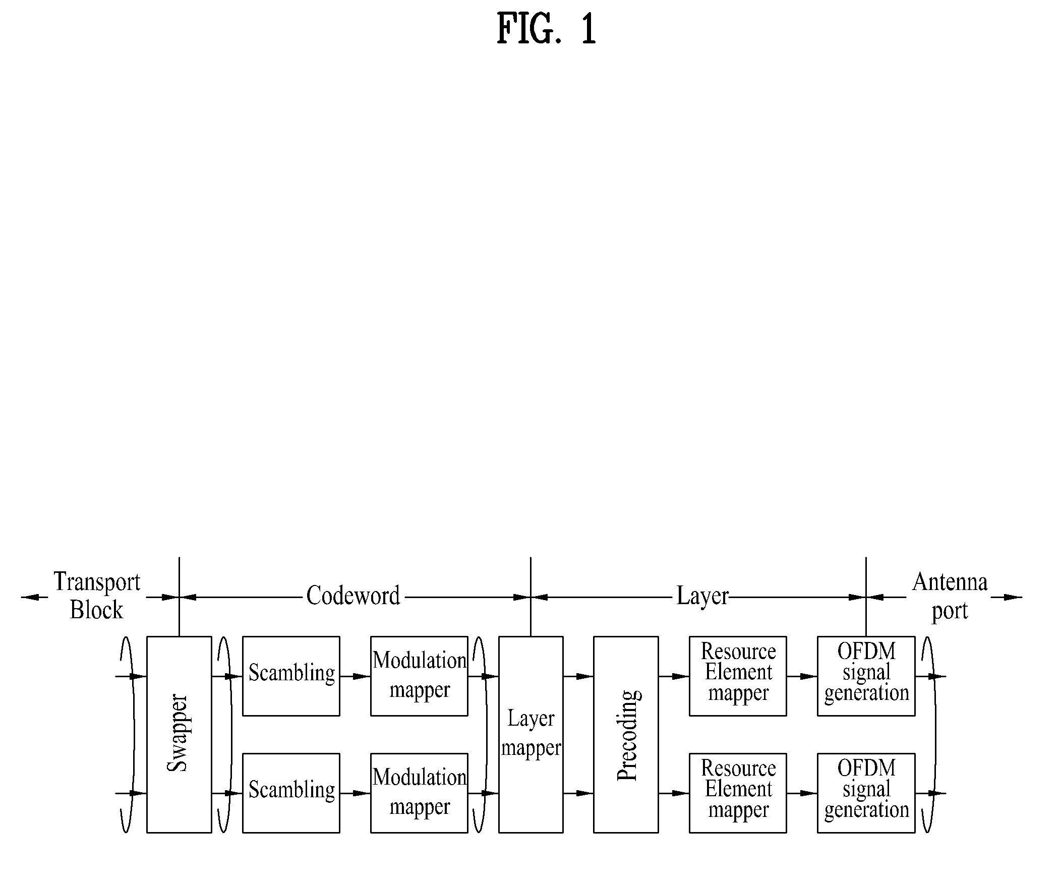
[0084]In the first embodiment, the transport block to codeword swap flag is used as a codeword indicator.

[0085]According to definition of the existing DCI 2A format, if one of two transport blocks is enabled, the transport block to codeword swap flag is reserved and the transport blocks 1 and 2 are mapped with codeword 0 (see Table 2). This embodiment suggests a method for using a transport block to codeword swap flag as an indicator of codeword mapped with one transport block if one of two transport blocks is enabled. In other words, the transport block to codeword swap flag can be reused as information indicating index of codeword used for single layer beamforming.

[0086]According to this embodiment, in a state that only one of two transport blocks is enabled, the transport block to codeword swap flag is not reserved and 1 bit value is given. In a state that only one of two transport blocks is enabled and the logic value of the swap flag is a first value, if the enabled transport b...

second embodiment

[0088]In the second embodiment, the transport block to codeword swap flag is used as a codeword indicator.

[0089]According to this embodiment, if only one of two transport blocks is enabled, the transport block to codeword swap flag is not reserved and 1 bit value is given. In a state that only one of two transport blocks is enabled, if a logic value of the swap flag is a first value (0 or off), it can be defined that the enabled transport block is mapped with codeword 0. Meanwhile, in a state that only one of two transport blocks is enabled, if a logic value of the swap flag is a second value (1 or on), it can be defined that the enabled transport block is codeword 1. Table 8 and Table 9 illustrate transport block to codeword mapping according to the second embodiment.

TABLE 8TB to CW mapping swap flag (one TB enabled) = 0TB 1TB 2CW 0 (enabled)CW 1 (disabled)enabledDisabledTB 1—disabledenabledTB 2—

TABLE 9TB to CW mapping swap flag (one TB enabled) = 1TB 1TB 2CW 0 (disabled)CW 1 (enab...

third embodiment

[0090]In the third embodiment, the transport block to codeword swap flag is used as a layer indicator.

[0091]According to this embodiment, in a state that only one of two transport blocks is enabled and the other one is disabled, if a logic value of the swap flag is a first value (0 or off), it can be defined that the user equipment acquires channel information of a first layer. And, if the logic value of the swap flag is a second value (1 or on), it can be defined that the user equipment acquires channel information of a second layer.

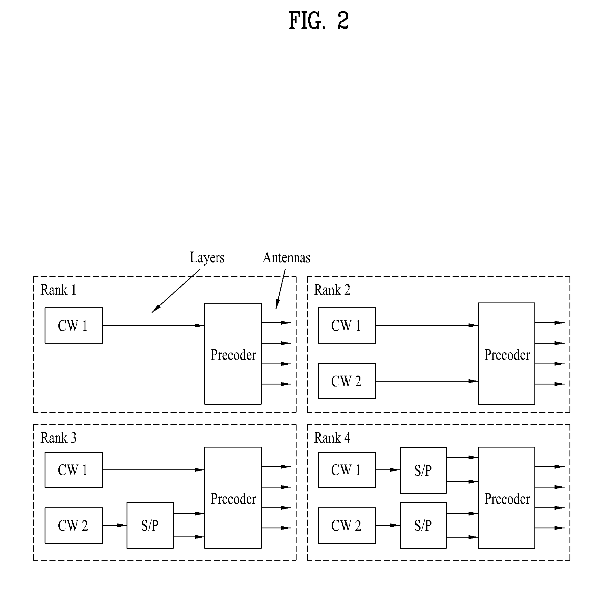
[0092]Meanwhile, in a state that only one of two transport blocks is enabled, if transmission is indicated by the transmit diversity scheme, the transmit diversity scheme based on the second layer can be used. The user equipment can acquire channel information of two channels from a dedicated reference signal transmitted through each layer. In this case, the codeword to layer mapping can follow the mapping rule of Table 4.


PUM


Abstract

A method and apparatus for transmitting a downlink signal in a multiple input multiple output (MIMO) wireless communication system is disclosed. A method for receiving a downlink signal from a base station to a user equipment in a multiple input multiple output (MIMO) system, which supports dual layer transmission based on first and second antenna ports, comprises receiving downlink control information (DCI) through a downlink control channel; and receiving downlink data through a downlink data channel, the downlink data including one or more of a first transport block and a second transport block, wherein the downlink control information includes a new data indicator (NDI) for each of the first and second transport blocks, and if the first transport block is disabled and the second transport block is enabled, the new data indicator for the first transport block indicates an antenna port through which the second transport block is received.

Description

CROSS-REFERENCE TO RELATED APPLICATIONS[0001]This application claims the benefit of U.S. Provisional Application No. 61 / 241,969, filed on Sep. 14, 2009, U.S. Provisional Application No. 61 / 242,286, filed on Sep. 14, 2009, U.S. Provisional Application No. 61 / 250,854, filed on Oct. 12, 2009, and U.S. Provisional Application No. 61 / 297,430, filed on Jan. 22, 2010, which are hereby incorporated by reference as if fully set forth herein.[0002]This application claims the benefit of the Korean Patent Application No. 10-2010-0027988, filed on Mar. 29, 2010, which is hereby incorporated by reference as if fully set forth herein.BACKGROUND OF THE INVENTION[0003]1. Field of the Invention[0004]The present invention relates to a wireless communication system, and more particularly, to a method and apparatus for transmitting a downlink signal in a multiple input multiple output (MIMO) wireless communication system.[0005]2. Discussion of the Related Art[0006]In a mobile communication system, a use...

Claims


Application Information

Patent Timeline
IPC IPC(8): H04L27/28
CPCH04B7/04H04W72/042H04B7/0413H04W72/23H04B7/0871H04W88/02H04W88/08
Inventor KO, HYUN SOOLEE, MOON ILKOO, JA HOCHUNG, JAE HOONIHM, BIN CHUL
Owner LG ELECTRONICS INC
Why Eureka
Try Eureka