Medical X-ray apparatus

Active Publication Date: 2011-03-17
MORITA MFG CO LTD
View PDF7 Cites 39 Cited by
  • Summary
  • Abstract
  • Description
  • Claims
  • Application Information

AI Technical Summary

Benefits of technology

[0031]According to the present invention, the direction intersecting with scan direction is defined as a height direction, at least one of both ends of width of the X-ray beam in the height direction is set at an optional position in accordance with the position of an interested area of the object, and the X-ray restricted in the height direction is irradiated only on the interested area of the object, thereby reducing X-ray exposure amount on the object.
[0032]According to the structure in which the width of the X-ray beam in scan direction intersecting with the height direction of the X-ray radiation area is restricted, the X-ray amount exposed on the object can be further reduced.
[0033]According to the structure in which a position of at least one of both ends of the width of the X-ray beam in the height direction of the X-ray radiation area is changed in the height direction, the width of the X-ray in the height direction can be dynamically changed depending on the shape of the interested area, thereby reducing the X-ray exposure amount on the area around the interested area.
[0034]According to the structure wherein the medical X-ray apparatus comprises a moving mechanism for moving the supporting part at least in the height direction with respect to the object to change the radiating position of the X-ray beam in the

Problems solved by technology

In addition, the panoramic radiography apparatus in the patent citation 2 discloses restriction of X-ray beam in a scanning d

Method used


Image

  • Medical X-ray apparatus
  • Medical X-ray apparatus
  • Medical X-ray apparatus

Examples


first embodiment

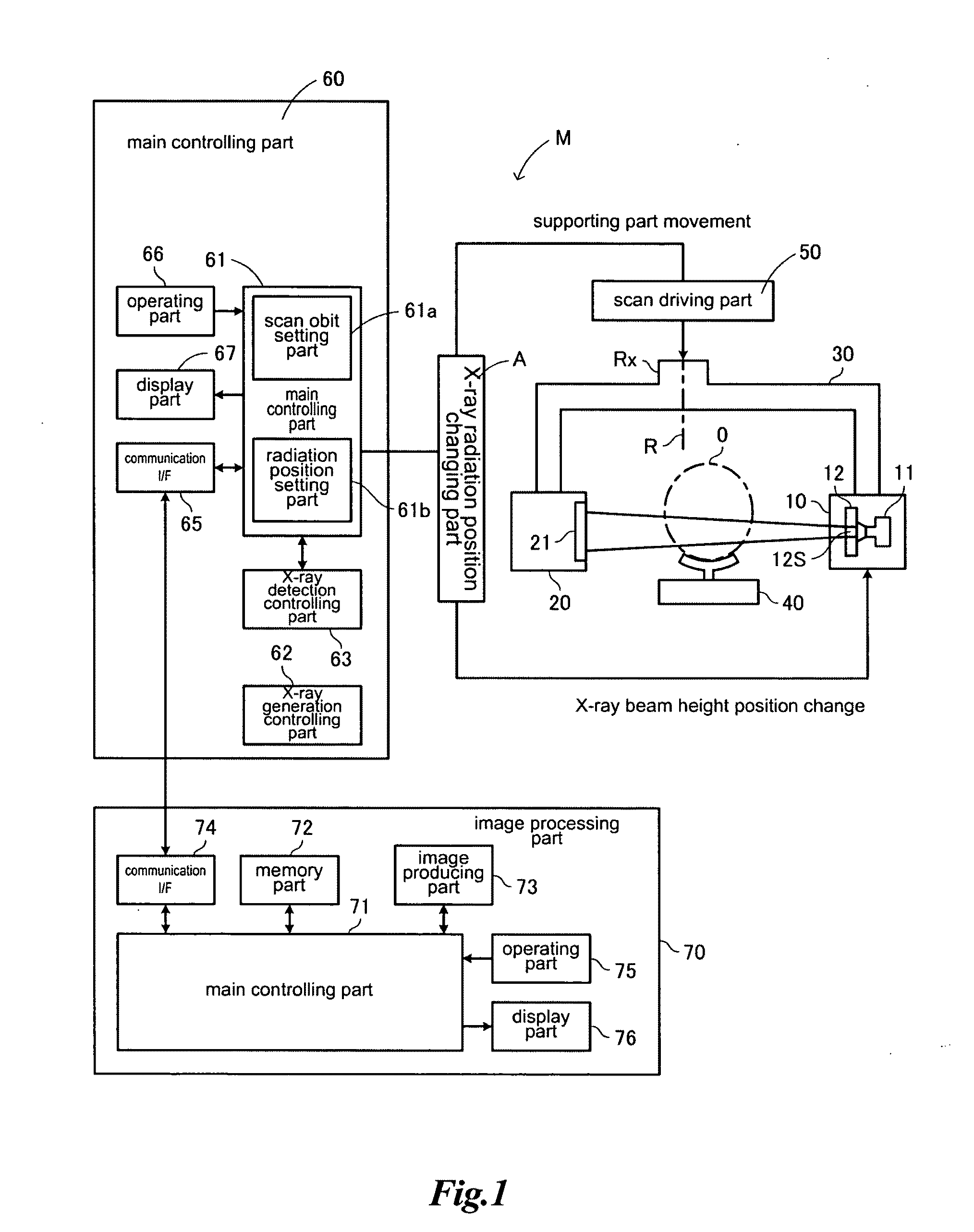
[0166]The medical X-ray apparatus M in FIG. 1 can execute partial panoramic radiography in which radiography is executed only on a local area which is a part of a curved sectional plane area SA of the entire dental arch S in addition to the above-mentioned entire panoramic radiography.

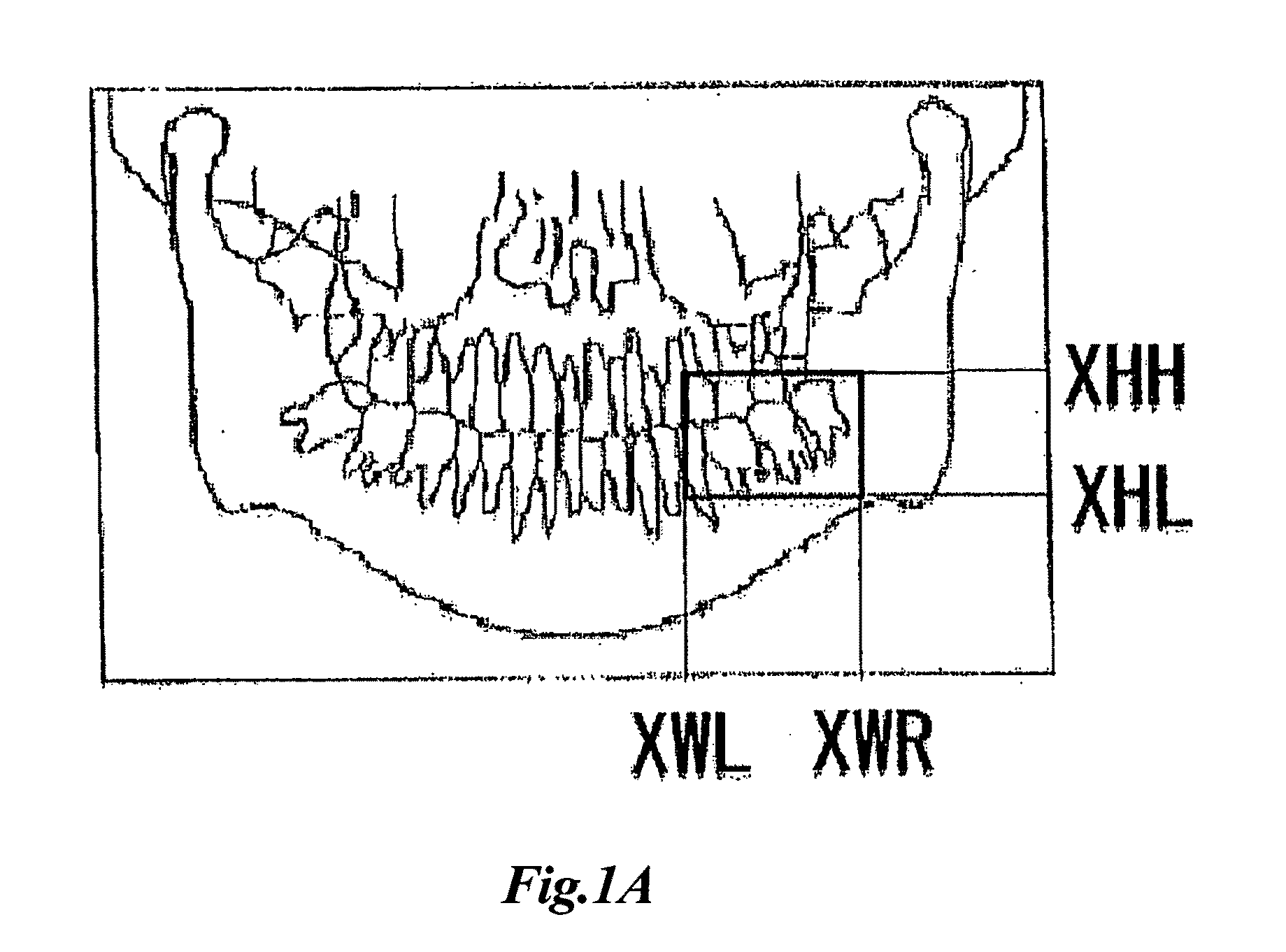
[0167]For example, as shown in FIG. 3, when partial panoramic radiography is executed on a local area SB only around the front teeth, X-ray beam XB from the X-ray generator 11 of the X-ray generating part 10 is irradiated in a manner such that the X-ray beam XB to be irradiated on the object to be examined “O” forms only a part Lb of an envelope curve La (solid lines in FIG. 3). In the figure, the local area SB which substantially includes two front teeth, and left and right neighbor teeth is shown in the figure. Accordingly, the X-ray detecting part 20 outputs a plurality of frame images of the X-ray transmitted image on the local area SB from the detector 21 as image data. Thus, the medical X-ray app...

second embodiment

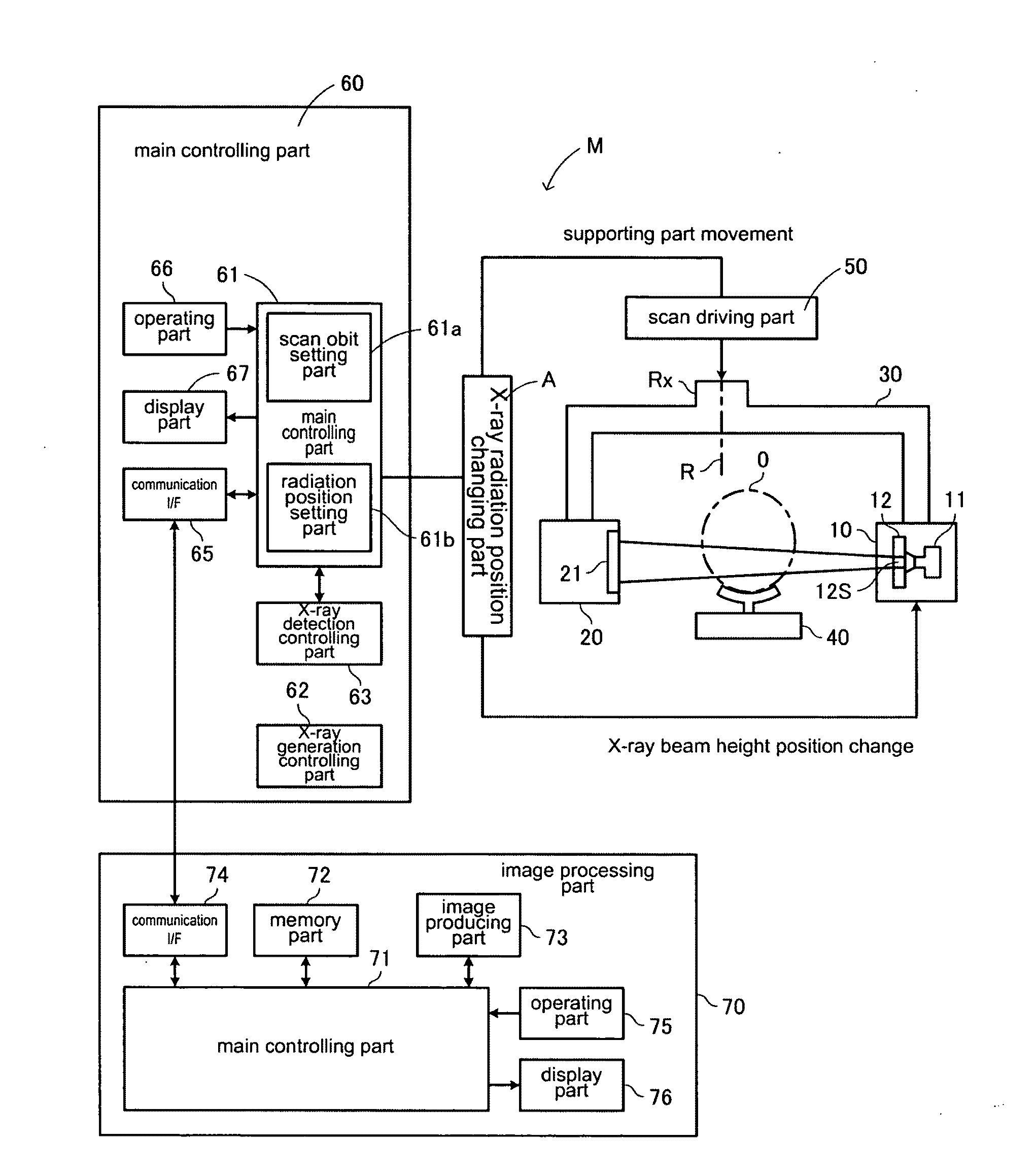
[0182]FIG. 7 shows a basic structure of a medical X-ray apparatus MA. This apparatus MA is provided with, as mentioned in the medical X-ray apparatus M of FIG. 1, the X-ray generator 11, the X-ray generating part 10 having the radiation area restricting part 12, the X-ray detecting part 20 having the X-ray detector 21, the supporting part 30, the object holding part 40, the scan driving part 50, the main body controlling part 60 and the image processing part 70, and further provided with a radiation area restricting part driving mechanism 13.

[0183]The second embodiment is characterized by using the radiation area setting part 61b to control the radiation area restricting part driving mechanism 13 in such a structure that the radiation area restricting part 12 changes the shape of the opening 12S which restricts the X-ray irradiated from the X-ray generator 11, and the radiation area restricting part driving mechanism 13 actuates, at the time of scanning with the X-ray beam XB, the r...

third embodiment

[0250]A third embodiment of the medial X-ray apparatus according to the present invention is explained hereinafter.

[0251]This medical X-ray apparatus has no difference to FIG. 7 as long as it is shown in the block diagram and therefore a block diagram thereof is omitted. The present embodiment is characterized in such that the radiation area restricting part driving mechanism 13 has a function which enables to change the opening width of the opening to be wider or narrower in the height direction during scanning with the X-ray beam XB.

[0252]FIGS. 13a and 13b show a basic principle of the scan control of the X-ray beam XB to be executed in the third embodiment.

[0253]Characteristics of the scan control of the X-ray beam XB are explained in comparison with the second embodiment. In the second embodiment, as shown in FIG. 9b, the X-ray beam XB is displaced without changing a width thereof in the height direction during scanning. It is because a position of the opening 12S in the height ...


PUM


Abstract

A medical X-ray apparatus comprising a supporting part for supporting an X-ray generator and a two-dimensional X-ray detector while interposing an object to be examined therebetween, a radiation area restricting part for restricting a radiation area of X-ray generated from the X-ray generator, and a scan driving part for scanning the object with the X-ray restricted by the radiation area restricting part as X-ray beam and for executing radiography. A direction intersecting with X-ray scan direction is defined as a height direction, the apparatus further comprises a radiation area setting part for setting at least one of both ends of width of the X-ray beam in the height direction at a desired position in accordance with the position of an interested area of the object; and the X-ray beam is irradiated only to the radiation area as set by the radiation area setting part with its beam width in height direction restricted by the radiation area restricting part.

Description

TECHNICAL FIELD[0001]The present invention relates to a medical X-ray apparatus for obtaining the information on a curved sectional plane by X-ray projection and obtaining a two-dimensional panoramic X-ray image.BACKGROUND ART[0002]A medical X-ray apparatus has an X-ray generator for projecting X-ray and an X-ray detector for receiving the X-ray from the X-ray generator, receives the X-ray generated at the X-ray generator and transmitted through an object to be examined, thereby obtaining an X-ray transmitted image based on the transmitted X-ray amount. In case of panoramic radiography, X-ray is projected while the X-ray generator and the X-ray detector are moved around the object along a predetermined orbit and a two-dimensional panoramic X-ray image of a curved sectional plane is obtained.[0003]The applicant of this invention has proposed a digital panoramic radiography apparatus in which the X-ray detector is a two-dimensional X-ray detector and a panoramic X-ray image on an opti...

Claims


Application Information

Patent Timeline
IPC IPC(8): A61B6/14G01N23/04A61B6/00
CPCA61B6/14A61B6/469A61B6/4233
Inventor SUZUKIYOSHIKAWA, HIDEKIYOSHIMURA, TAKAHIROHONJO, MAKOTO
Owner MORITA MFG CO LTD
Why Eureka
Try Eureka