Automated turnout inspection

a turnout inspection and automatic technology, applied in the direction of railway signalling and safety, instruments, computing, etc., can solve the problems of affecting the safety and reliability of rail transportation, the derailment of a train traveling on the track, and significant property damage and injury to passengers, crew and bystanders, so as to reduce the reliance on field measurements, enhance the turnout inspection approach, and frequent, comprehensive and convenient analysis of turnout condition

Active Publication Date: 2011-03-17
HARSCO CORP
View PDF27 Cites 71 Cited by
  • Summary
  • Abstract
  • Description
  • Claims
  • Application Information

AI Technical Summary

Benefits of technology

[0018]The methods disclosed herein are part of a system for identifying certain classes of switch or turnout rail conditions which can lead to derailments, and for enhancing the turnout inspection approach currently used. The use of this method as an integrated part of the rail profile monitoring program will reduce reliance on field measurements and will also allow more frequent, comprehensive, and convenient analysis of turnout condition.

Problems solved by technology

The condition of the railroad track greatly impacts safety and reliability of rail transportation.
Failure or degradation of various rail components of a railroad track can cause derailment of a train traveling on the track.
Such derailment can cause significant property damage and injury to passengers, crew and bystanders.
However, the quality of visual inspection is generally poor, especially when the visual inspection is performed from a hi-railer, which is a vehicle that has been modified to drive on railroad tracks.
The limitation of this prior art method of inspecting railroad components is that it is very difficult for the inspector to see small defects or damage in the railroad components while driving the hi-railer.
This limitation is exacerbated by the fact that defects or damage to the rail portions of the turnouts, i.e. switch points, stock rails, frogs and closure rails, are especially difficult to see.
However, inspection performed on foot is a slow and tedious process, requiring many hours to inspect several miles of railroad track.
The significant limitation of the inspection vehicle disclosed in Trosino et al. and the method taught therein requires the inspector to continually perform visual inspection of the railroad track while traveling on the railroad track, such inspection being not much better in quality than the conventional inspection method from a hi-railer noted above.
Therefore, whereas the railcar vehicle of Trosino et al. is appropriate for inspecting a railroad track for large anomalies which are easily visible to the inspector, such as the presence of weeds, blocked drain, etc., the described inspection vehicle does not allow facilitated inspection of smaller rail components or smaller defects associated therewith.
Other systems, such as the VISTA system, a product of Loram, Inc., are of more limited application, primarily on rail grinders.
While these systems all generate digitized rail head profiles for the running rails, the exact extent of the measured rail head is limited by the number of cameras used and the “shadow” of the rail heads themselves.
Thus, in all cases, they do not get a complete rail head image but a full top-of-rail profile, parts of the side of the rail head, and portions of the rail web and base.
The bottom of the rail head is almost always obscured and lost, as is the bottom of any lip on the rail head.
In addition, while these systems generate digitized rail head profiles for the running rails, they do not analyze or generate digitized profiles for switches, frogs or other such components of turnouts.
The usefulness of such prior systems has been limited to running rails.

Method used


Image

  • Automated turnout inspection
  • Automated turnout inspection
  • Automated turnout inspection

Examples


Embodiment Construction

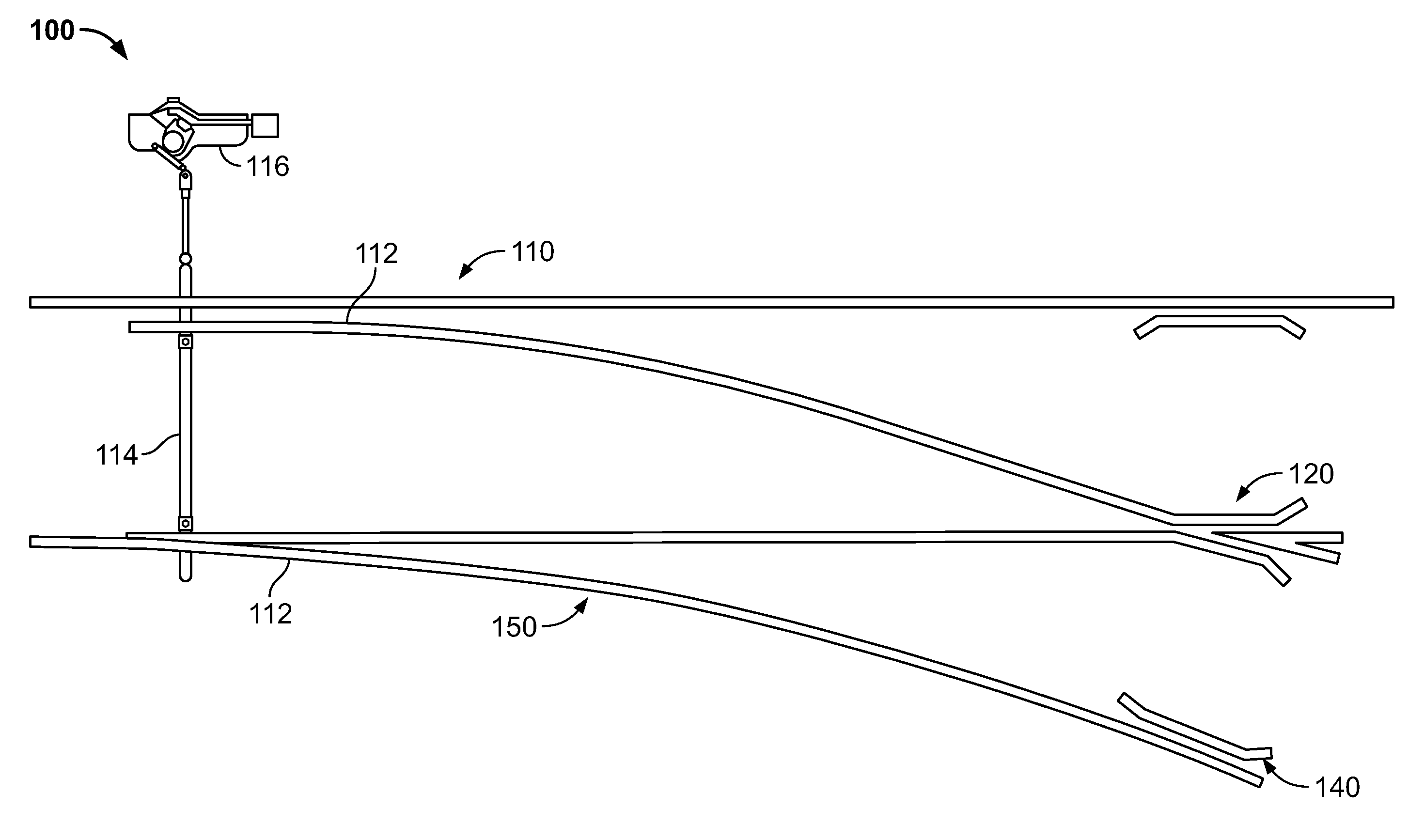
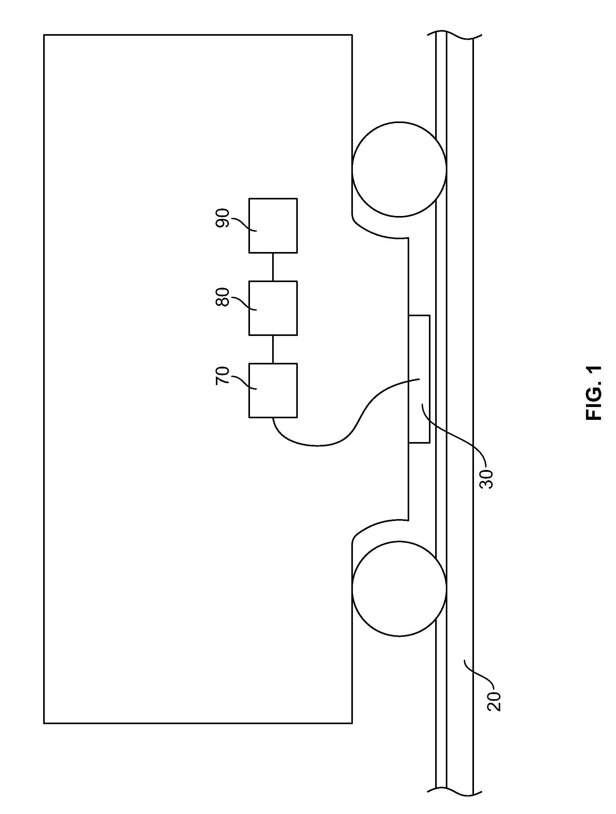
[0030]FIG. 1 shows an illustration of an inspection system 10 in accordance with one example embodiment of the present invention that facilitates inspection of rail components while traveling on the railroad track. As can be appreciated, only one side of a respective railroad track 20 is shown in FIG. 1. As will be evident from the discussion below, the inspection system 10 facilitates inspection of the rail portion of turnouts, which include, but are not limited to, the switch points, stock rails, frog and closure rails.

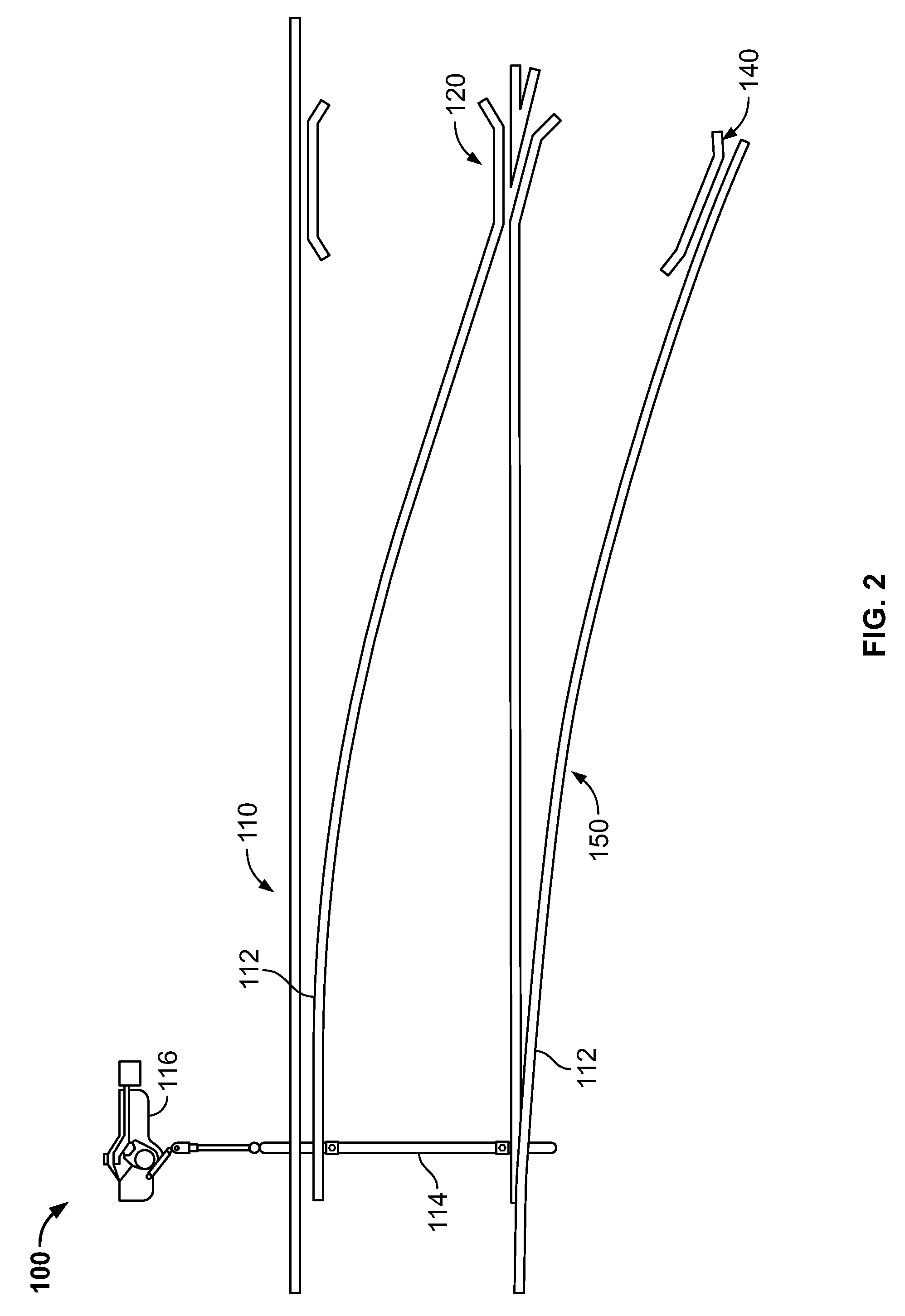
[0031]A turnout is a track device for diverting trains from the running track to other tracks. It represents an arrangement by which vehicles travel from one track to another. Two turnouts are used for the construction of a crossover. Turnouts, crossings, and other special track work are design “discontinuities” in the railroad track structure necessitated by the physical requirements for moving a rail vehicle from one track to another or for crossing tracks. They g...


PUM


Abstract

A method of inspecting a turnout of a track includes the steps of: capturing images of the components of the turnout; converting each image into a set of coordinates that traces the transverse cross-section of a rail profile; analyzing the rail profile to determine if the rail profile is a profile of arunning rail portion or a component. Upon determination that the image represents a component, taking measurements of the rail profile and applying virtual gauges to the rail profile to check for potentially dangerous conditions of the component; and generating a summary of each cross-section of the rail profile of the component indicating problem areas. The method is used for identifying certain classes of switch or turnout rail conditions which can lead to derailments, and for enhancing the turnout inspection approach currently used. The use of this method as an integrated part of the rail profile monitoring program will reduce reliance on field measurements and will also allow more frequent, comprehensive, and convenient analysis of turnout condition.

Description

FIELD OF THE INVENTION[0001]The present invention is directed to a system and a method for inspecting rail components of a railroad track, and in particular for inspecting the rail portion of turnouts, which include the switch points, stock rails, frog and closure rails.BACKGROUND OF THE INVENTION[0002]Maintaining proper conditions of rail components of a railroad track is of paramount importance in the railroad transportation industry. Rail components include joint bars, fasteners, switches, frogs, ties, ballast, etc., as well as the rail segments themselves which form the railroad track. The condition of the railroad track greatly impacts safety and reliability of rail transportation. Failure or degradation of various rail components of a railroad track can cause derailment of a train traveling on the track. Such derailment can cause significant property damage and injury to passengers, crew and bystanders.[0003]Visual inspection is one way to monitor the condition of railroad tra...

Claims


Application Information

Patent Timeline
Patent Type & Authority Applications(United States)
IPC IPC(8): G06K9/00
CPCB61K9/08B61L2205/04B61L23/045B61L23/042
Inventor ZAREMBSKI, ALLAN M.EUSTON, TODD L.PALESE, JOSEPH W.
Owner HARSCO CORP
Why Eureka
Try Eureka