Developing device and image forming apparatus provided with same

a technology of developing device and image forming apparatus, which is applied in the direction of electrographic process apparatus, instruments, optics, etc., can solve the problems of inability to focus a magnetic line, inability to favorably charge toner, and deterioration of the carrier, etc., and achieve the effect of favorable toner imag

Inactive Publication Date: 2011-03-17
KYOCERA DOCUMENT SOLUTIONS INC
View PDF3 Cites 5 Cited by
  • Summary
  • Abstract
  • Description
  • Claims
  • Application Information

AI Technical Summary

Benefits of technology

[0014]Accordingly, in light of the above circumstances, an object of the present invention is to provide a developing device and an image forming apparatus provided with this in which a developer layer having a uniform layer thickness is formed by suppressing accumulation of developer, thereby enabling a favorable toner image to be formed.

Problems solved by technology

However, the developer tends to accumulate in a space on an upstream side from the regulating blade as viewed from the rotation direction of the developing roller, and within this space, toner deterioration due to bury of external additives to the toner or separation of external additives from the toner, or carrier deterioration due to adhesion of toner external additives to the carrier occurs since, for example, the developers rub against each other.
When the developer deteriorates in this manner, the toner cannot be favorably charged.
Furthermore, when the developer, which is a magnetic substance, accumulates on the upstream side of the regulating blade, it is difficult to focus a magnetic line, which is produced between the regulating blade and the developing roller, on the regulating blade, and the regulating force of the regulating blade does not stabilize.
As a result, it becomes difficult to form a uniform layer thickness of developer on the circumferential surface of the developing roller, and thus also difficult to form a favorable toner image.
However, in the developing device of the first prior art, a step is formed between the end surface of the regulating blade and the guiding conveyance surface of the carrier returning member due to factors such as dimensional precision and installation precision of the carrier returning member, and therefore the developer tends to accumulate in the step.
As described above, when the developer accumulates, the developer deteriorates and it becomes difficult to form a developer layer having a uniform layer thickness on the circumferential surface of the developing roller.
Furthermore, since the elastic member in the second prior art is a member having a thickness enough to occupy the upstream side space, in the case where the elastic member deforms due to heat produced in the developing device, the extent of thermal deformation tends to increase.
Furthermore, when the elastic member deforms, the position of the conveyance amount regulating surface changes, and therefore in consideration of this change, the step between the regulating surface of the regulating blade and the conveyance amount regulating surface becomes undesirably larger, so that the developer tends to accumulate.
Thus, as described above, when the developer accumulates, developer deterioration occurs and, as a result, it becomes difficult to form a toner layer having a uniform layer thickness on the circumferential surface of the developing roller.

Method used


Image

  • Developing device and image forming apparatus provided with same
  • Developing device and image forming apparatus provided with same
  • Developing device and image forming apparatus provided with same

Examples


first embodiment

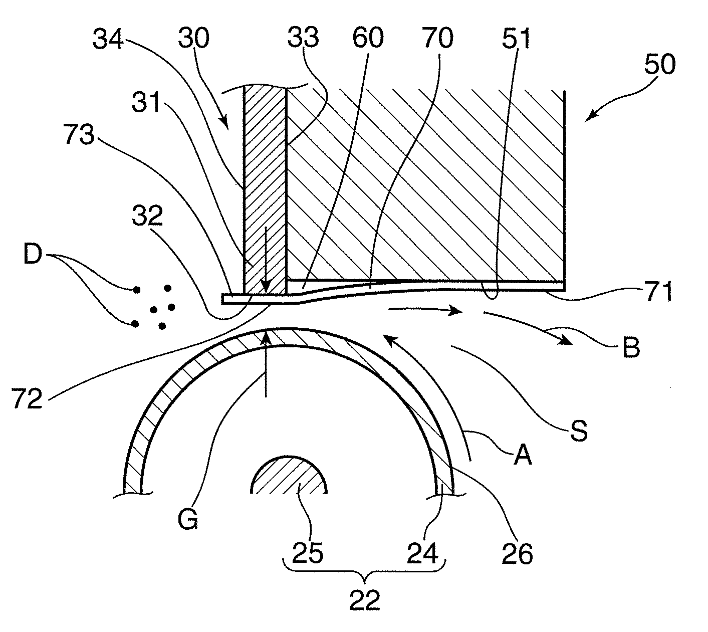
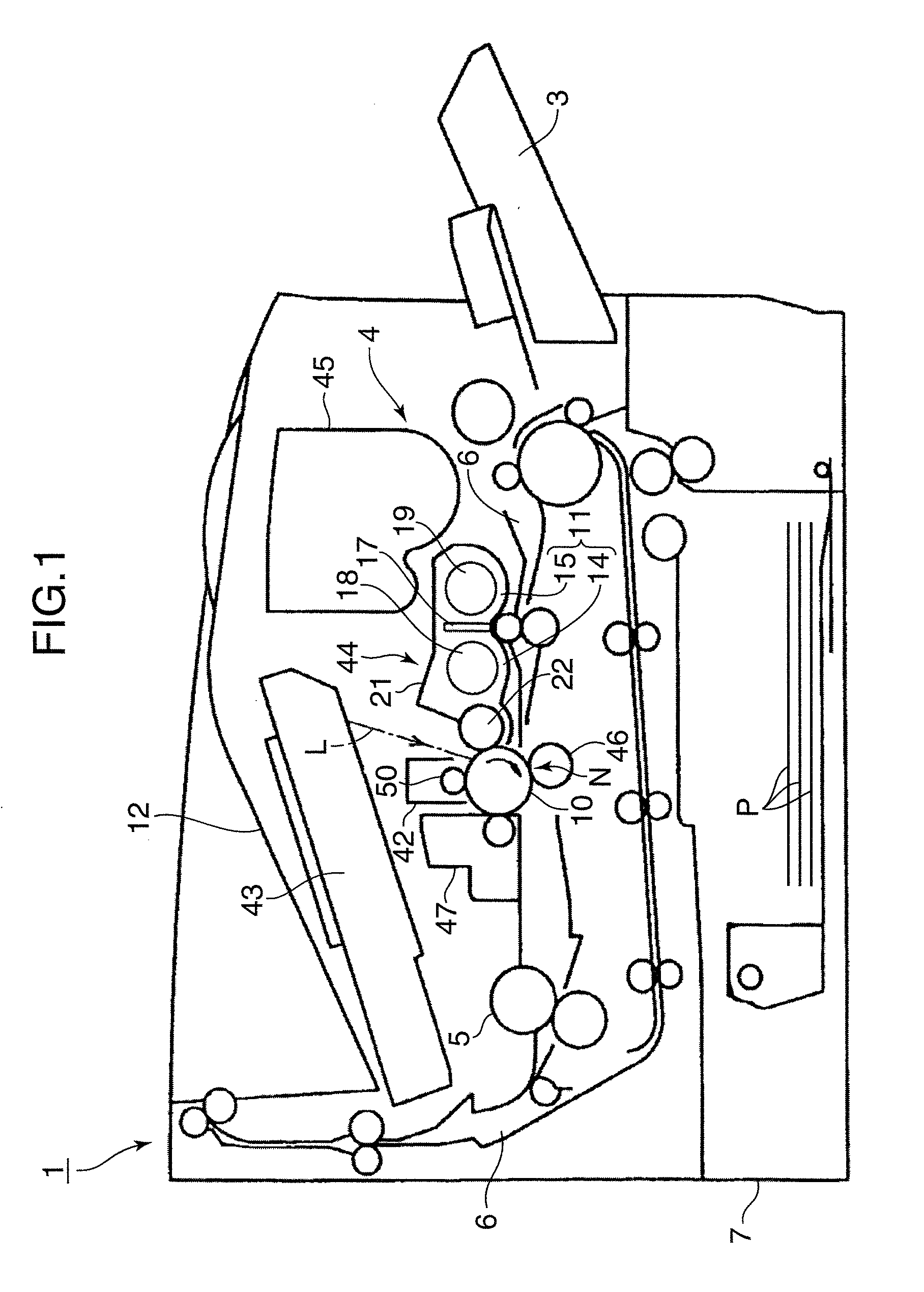
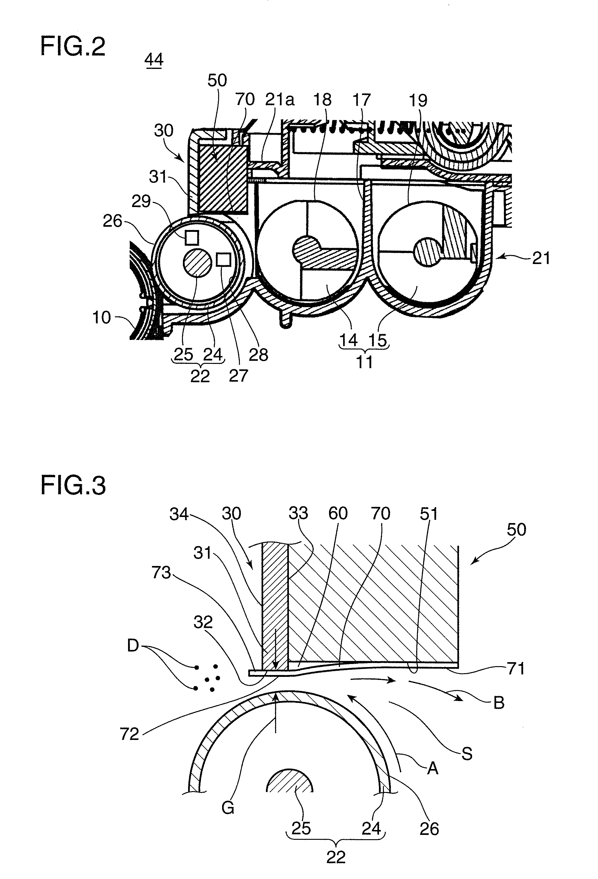
[0036]Hereinafter, detailed description is given regarding the developing device 44 according to a first embodiment with reference to FIG. 2 in addition to FIG. 1. FIG. 2 is an enlarged view of the developing device 44. The developing device 44 uses a two-constituent developer containing a mixture of a nonmagnetic toner and a magnetic carrier, and as shown in FIG. 1 and FIG. 2, includes, as fundamental elements, a development vessel 21 that defines an internal space of the developing device 44, a developer storing portion 11 that is formed in bottom walls of the development vessel 21, and a developing roller 22 arranged at a development opening of the development vessel 21.

[0037]The developer storing portion 11 is constituted by two neighboring developer storage chambers 14 and 15 that extend in a longitudinal direction (a vertical direction with respect to the paper plane of FIG. 1) of the developing device 44. The developer storage chambers 14 and 15 are partitioned from each othe...

second embodiment

[0068]Next, description is given regarding a developing device 80 according to a second embodiment with reference to FIG. 5 and FIG. 6. In the second embodiment, the developer regulating blade 30 includes a first blade portion 35 that is formed from a nonmagnetic material such as aluminum and a second blade portion 36 that is formed from a magnetic material such as SUS430.

[0069]The first blade portion 35 is a plate shaped member extending along the axial direction of the developing sleeve 24 and is provided with an end 37 extending toward the outer circumferential surface 26 of the developing sleeve 24. The end 37 is provided with a first opposing surface 38 that opposes the outer circumferential surface 26 of the developing sleeve 24.

[0070]The second blade portion 36 is a plate shaped member extending along the axial direction of the developing sleeve 24 in the same manner as the first blade portion 35, and is positioned on one side surface 39 of the first blade portion 35 facing t...

third embodiment

[0078]FIG. 7 shows a developing device 90 according to a third embodiment. Except for the feature that the developer returning member 50 is not used, the configuration of the third embodiment is the same configuration as the second embodiment. In the third embodiment, since the developer returning member 50 is not used, the sheet member 70, as shown in FIG. 8, is attached from one side surface (right side surface in FIG. 8) 66 of the second blade portion 36 of the developer regulating blade 30 facing the inside space of the development vessel 21, via the second opposing surface 62 of the second blade portion 36 and the first opposing surface 38 of the first blade portion 35, which constitute the first regulating surface 32, extending to a side surface (left side surface in FIG. 8) 64 facing outside the developing device 90 at the first blade portion 35.

[0079]In the third embodiment also, the first opposing surface 38 of the first blade portion 35 and the second opposing surface 62 o...


PUM


Abstract

A developing device includes a developer storing portion, a developer carrying body, a first regulating member having a first regulating surface regulating a layer thickness of the developer on the developer carrying body, a second regulating member having a second regulating surface that is set so as to gradually become apart from the developer carrying body toward the upstream side with respect to the rotation direction of the developer carrying body to regulate an amount of the developer conveyed to the first regulating surface, the second regulating surface being arranged with a step formed between the second regulating surface and the first regulating surface, and a sheet member so attached to the second regulating surface as to cover at least a portion of the step between the first regulating surface and the second regulating surface.

Description

BACKGROUND OF THE INVENTION[0001]1. Field of the Invention[0002]The present invention relates a developing device that forms a toner image on a predetermined image carrying body and to an image forming apparatus provided with the same.[0003]2. Description of the Related Art[0004]Image forming apparatuses that use an electrophotographic method, such as copiers, printers, fax machines, and multifunction machines that combine these, include a developing device supplying a toner to an image carrying body (for example, a photosensitive drum or transfer belt) to form a toner image on the image carrying body.[0005]The developing device includes, as fundamental elements, a developer storing portion which stores a developer constituted by a toner and a carrier, a developing roller which forms a toner image on an image carrying body by receiving the developer from the developer storing portion and supplying the developer to the image carrying body, and a regulating blade which is arranged in ...

Claims


Application Information

Patent Timeline
Patent Type & Authority Applications(United States)
IPC IPC(8): G03G15/09
CPCG03G15/0812
Inventor WADA, MINORUOJIMA, SEISHIMABUCHI, SAYO
Owner KYOCERA DOCUMENT SOLUTIONS INC
Why Eureka
Try Eureka