Transfer device and image forming apparatus using same

a technology of transfer device and image forming apparatus, which is applied in the direction of electrographic process apparatus, instruments, optics, etc., can solve the problems of degrading imaging quality, complicating maintenance of proper tension of intermediate transfer belt, and causing the drift of the intermediate transfer belt laterally

Active Publication Date: 2011-03-17
RICOH KK
View PDF18 Cites 44 Cited by
  • Summary
  • Abstract
  • Description
  • Claims
  • Application Information

AI Technical Summary

Problems solved by technology

Consequently, if such rollers are deformed or are not properly installed, desired parallelism of the intermediate transfer belt between the rollers is not obtained, causing the intermediate transfer belt to drift laterally, that is, in a width direction thereof, as it rotates.
As a result, distortion or color drift may occur in a resulting output image, thus degrading imaging quality.
Unfortunately, a variety of factors complicate maintenance of the proper tension on the intermediate transfer belt.
Unfortunately, moving the rollers causes a path along which the intermediate transfer belt moves to change, thereby changing undesirably the tension of the intermediate transfer belt.
As noted, when the tension of the intermediate transfer belt changes undesirably, the resistance of contact between the intermediate transfer belt and the rollers including the steering roller changes, thereby complicating efforts to control the position of the intermediate transfer belt in the main scanning direction.
As a result, the speed of the intermediate transfer belt fluctuates undesirably, causing distortion and/or color drift in the resulting output image.
As a result, the belt tension may be reduced and the belt thus loosened, thereby undesirably contacting other parts of the image forming apparatus and thus getting damaged.
Another difficulty deri

Method used


Image

  • Transfer device and image forming apparatus using same
  • Transfer device and image forming apparatus using same
  • Transfer device and image forming apparatus using same

Examples


Embodiment Construction

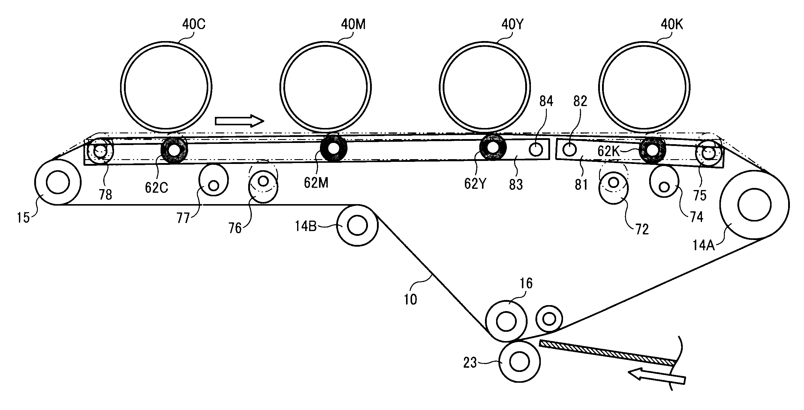
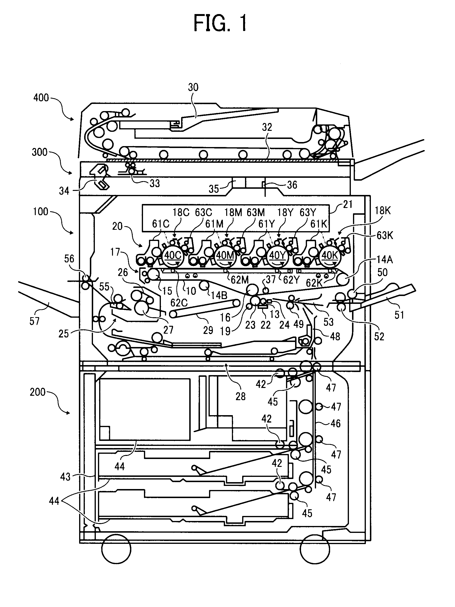
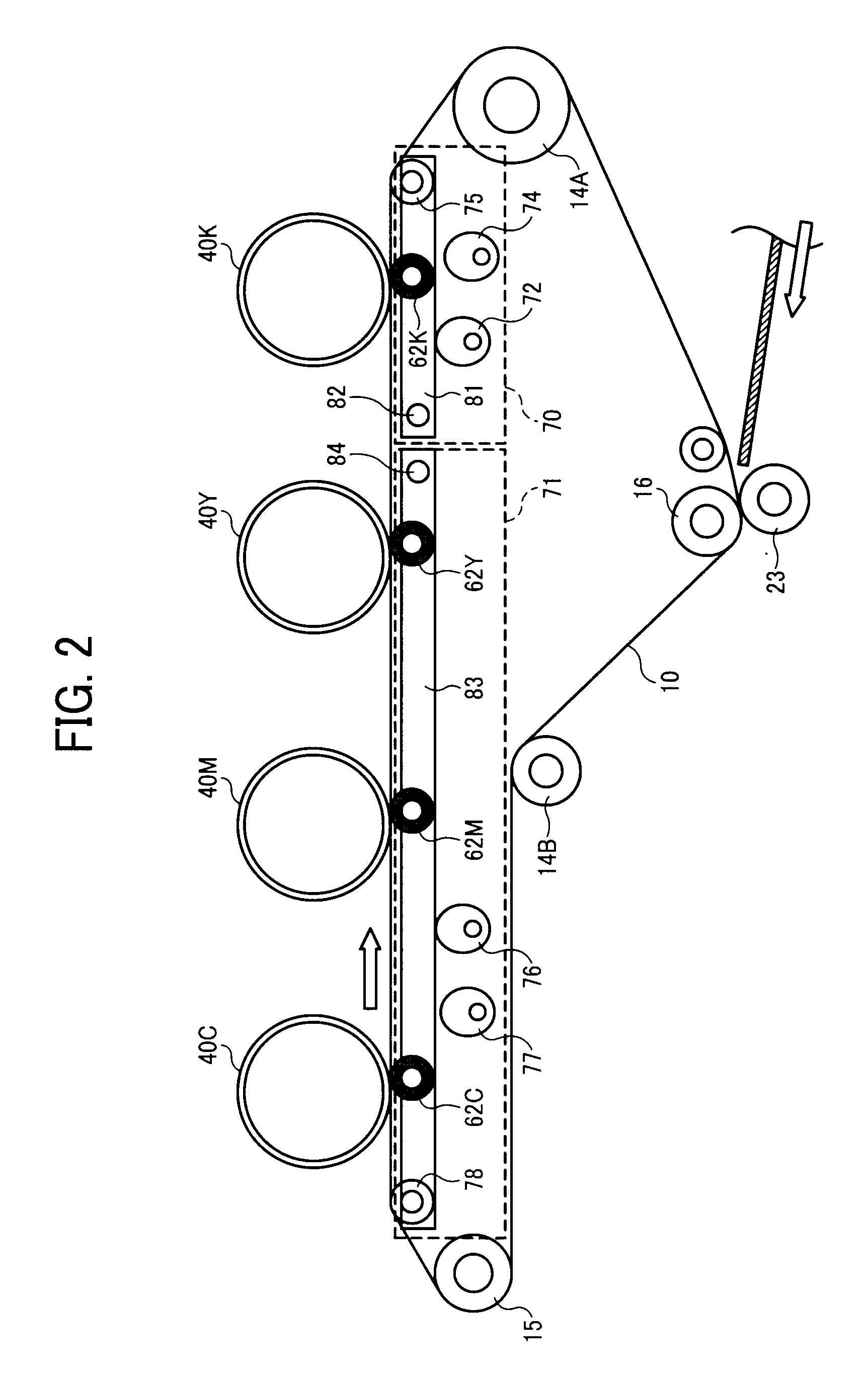
[0035]A description is now given of exemplary embodiments of the present invention. It should be noted that although such terms as first, second, etc. may be used herein to describe various elements, components, regions, layers and / or sections, it should be understood that such elements, components, regions, layers and / or sections are not limited thereby because such terms are relative, that is, used only to distinguish one element, component, region, layer or section from another region, layer or section. Thus, for example, a first element, component, region, layer or section discussed below could be termed a second element, component, region, layer or section without departing from the teachings of the present invention.

[0036]In addition, it should be noted that the terminology used herein is for the purpose of describing particular embodiments only and is not intended to be limiting of the present invention. Thus, for example, as used herein, the singular forms “a”, “an” and “the...


PUM


Abstract

A transfer device includes a plurality of rollers, a rotatable intermediate transfer belt wound around and stretched between the rollers, a transfer member disposed in the inner loop of the belt and facing an image bearing member of an image forming apparatus disposed at an outer circumference of the belt, to transfer an image formed onto the surface of the image bearing member when contacting the intermediate transfer belt, and a position adjuster to adjust the position of the intermediate transfer belt at different positions relative to the image bearing member. The positions include a contact state in which the intermediate transfer belt applied with a predetermined tension contacts the image bearing member, a first separation state in which the tensioned intermediate transfer belt separates from the image bearing member, and a second separation state in which the intermediate transfer belt separates further away from the image bearing member.

Description

CROSS-REFERENCE TO RELATED APPLICATIONS[0001]This patent application is based on and claims priority pursuant to 35 U.S.C. §119 from Japanese Patent Application No. 2009-213068, filed on Sep. 15, 2009 in the Japan Patent Office, which is hereby incorporated herein by reference in its entirety.BACKGROUND OF THE INVENTION[0002]1. Field of the Invention[0003]Exemplary aspects of the present invention generally relate to a transfer device that transfers an image formed on an image bearing member, and an image forming apparatus, such as copiers, facsimile machines, or printers, using the transfer device.[0004]2. Description of the Background Art[0005]Conventionally, image forming apparatuses such as copiers, facsimile machines, or printers include a developing device that develops what is called an electrostatic latent image formed on an image bearing member, for example, a photoreceptor, with toner to form a visible image, also known as a toner image; a transfer device that transfers th...

Claims


Application Information

Patent Timeline
IPC IPC(8): G03G15/01
CPCG03G15/161G03G15/1615G03G15/0136
Inventor ICHIHASHI, OSAMUMIMBU, RYUUICHISENGOKU, KENJIFUJITA, JUNPEI
Owner RICOH KK
Why Eureka
Try Eureka