
Battery array with reliable low-resistance connections

Inactive Publication Date: 2011-03-17
SANYO ELECTRIC CO LTD
View PDF7 Cites 43 Cited by
  • Summary
  • Abstract
  • Description
  • Claims
  • Application Information

AI Technical Summary

Benefits of technology

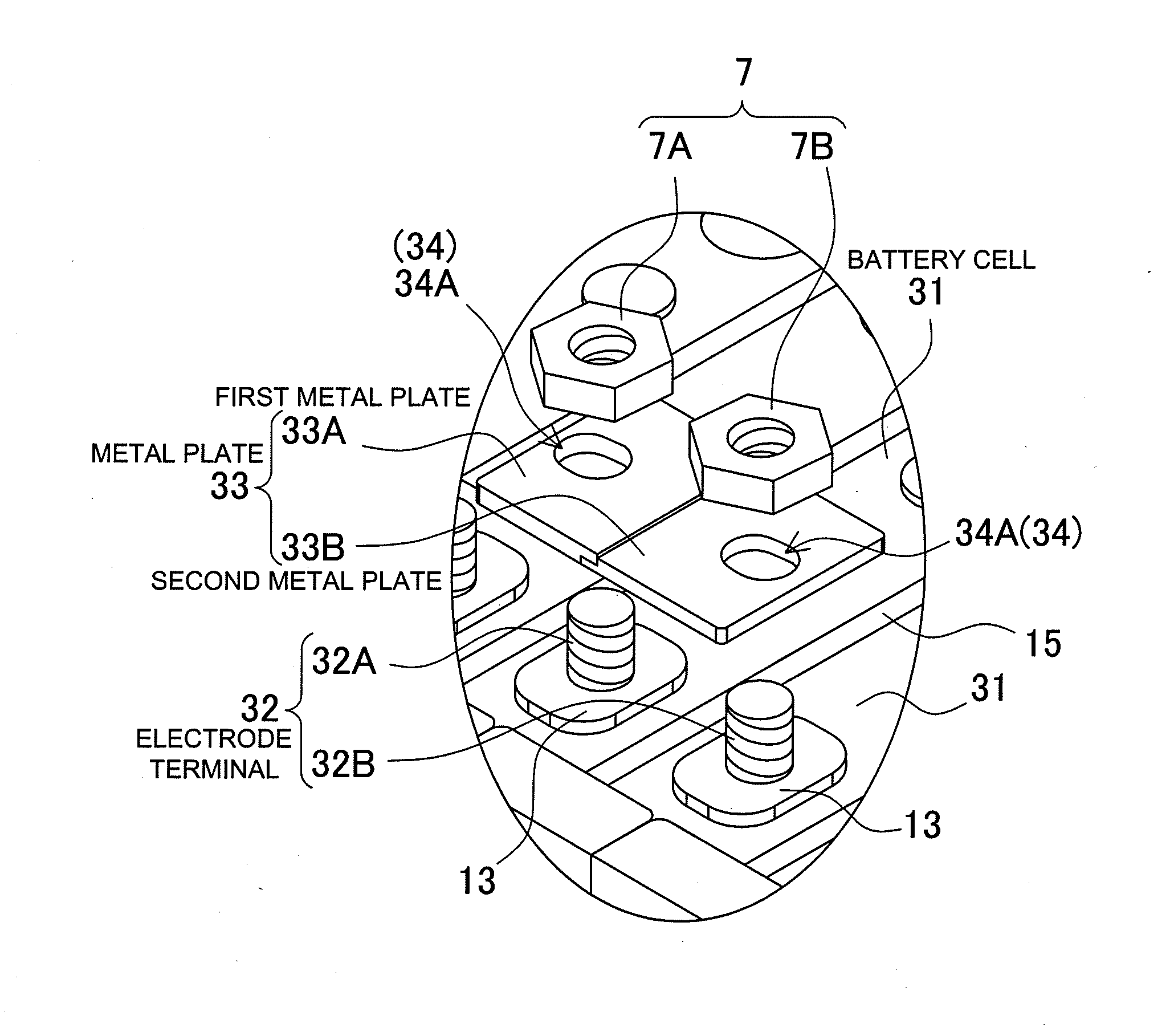
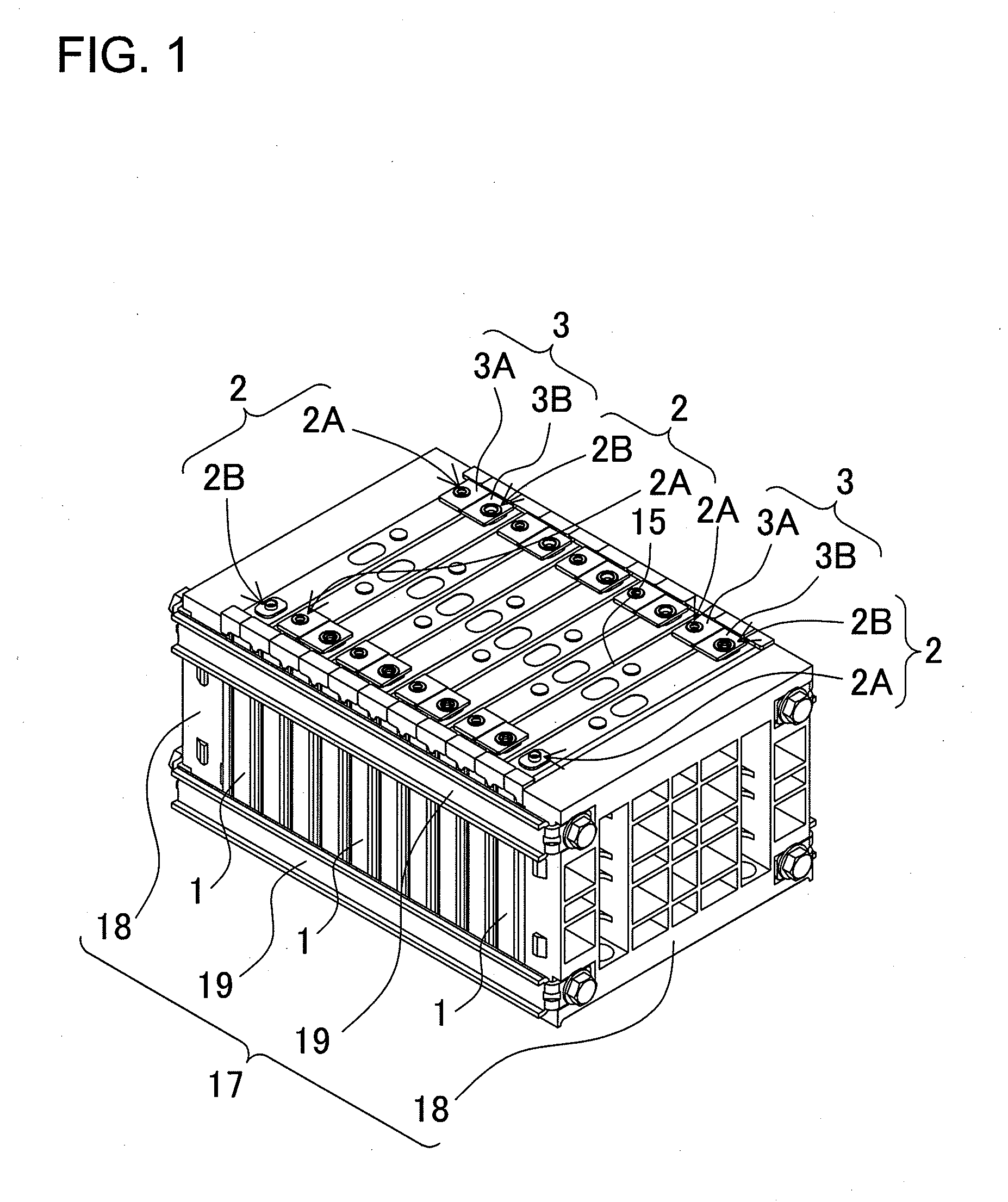
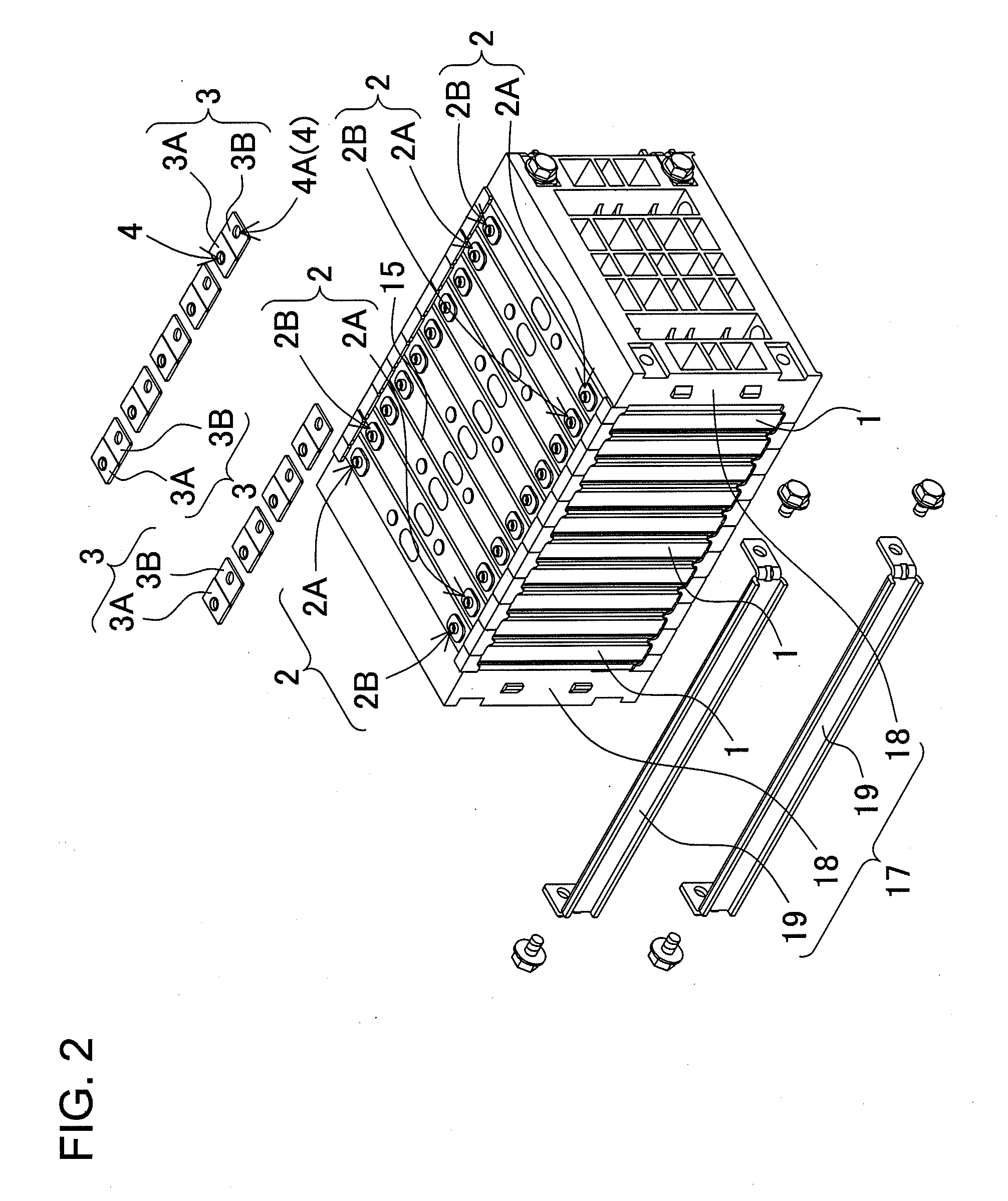
[0008]The battery array described above has the characteristic that it can connect battery cell electrode terminals in series or parallel with metal plates in a manner that maintains stable low resistance connections over a long period while connecting different type metals at the positive and negative electrode terminals of the battery cells. This is because the first metal plate that connects to one of the electrode terminals of a battery cell and the second metal plate that connects to a different electrode terminal are clad material joined at a junction between the positive and negative electrode terminal connecting regions. Clad material is not simply a laminate of different type metals, but rather is strongly joined together at the junction interface where the different metals are in an alloyed state. Accordingly, in a metal plate made of clad material, there is no ingress of water or air to the junction between the different metals, and galvanic corrosion does not occur at the junction interface. Therefore, metal plates that are dissimilar metal clad material joined at a junction between positive and negative electrode terminals have the characteristic that each electrode terminal can be connected with the same metal type to prevent galvanic corrosion and enable stable electrical connection over a long period.
[0010]The battery array described above has the characteristic that the clad material metal plates can be stably and reliably weld-attached to the electrode terminals while absorbing dimensional error in the battery cells and metal plates via the elongated holes. This is because error in the dimensions of the battery cells and the metal plates can be absorbed by electrode terminal insertion in the elongated holes. In addition, gaps formed by insertion of the electrode terminals in the elongated holes can be closed-off by welding rings, and electrical connection can be made without gaps by welding the welding rings.
[0011]In the battery array of the present invention, a welding ring 5, 25 can be either a crimping ring 2X formed by pressure-deformation to widen the upper end of an electrode terminal 2 inserted in an elongated hole 4A, or a metal ring 6 that is a sheet-metal piece separate from the electrode terminal 2 and provided with a center hole 6A for electrode terminal 2 insertion. In this battery array, welding rings formed as crimping rings by widening the ends of the electrode terminals can be weld-attached to the metal plates for reliable connection. Further, with welding rings that are metal rings separate from the electrode terminals, the metal rings can be weld-attached to the electrode terminals and metal plates for reliable electrical connection without putting a load on the electrode terminals.
[0014]In the battery array of the present invention, the metal plates 3, 23, 33, 43, 53 can be first metal plates 3A, 23A, 33A, 43A, 53A and second metal plates 3B, 23B, 33B, 43B, 53B joined at junctions with step-shaped interfaces. This battery array has the characteristic that since the junction interfaces are step-shaped, the first metal plates and second metal plates can be stably and reliably joined in a robust manner.
[0015]In the battery array of the present invention, the battery cells 1, 31 can be lithium ion batteries. This battery array has the characteristic that since the battery cells are lithium ion batteries, it can increase charging and discharging capacities while being light-weight.

Problems solved by technology

This is because error in the dimensions of the battery cells and the metal plates can be absorbed by electrode terminal insertion in the elongated holes.

Method used


Image

  • Battery array with reliable low-resistance connections
  • Battery array with reliable low-resistance connections
  • Battery array with reliable low-resistance connections

Examples


Embodiment Construction

)

[0035]The following describes embodiments of the present invention based on the figures.

[0036]The battery array of the present invention is primarily installed on-board an electric-powered vehicle such as a hybrid car or electric automobile (electric vehicle EV), and is used as a power source to supply power to a driving motor to drive the vehicle.

[0037]The battery array shown in FIGS. 1-3 has a plurality of battery cells 1 stacked and held together in a manner insulating individual battery cells 1. The battery cells 1 are rectangular battery cells. Further, the rectangular battery cells 1 are lithium ion rechargeable batteries. However, the battery array of the present invention is not limited to battery cells that are rectangular, and also is not limited to lithium ion rechargeable batteries. Any batteries that can be charged, such as nickel hydride batteries, can also be used as the battery cells. As shown in FIG. 4, a rectangular battery cell has an electrode unit 10, which is ...


PUM


Abstract

The battery array is provided with a plurality of battery cells 1 having positive and negative electrode terminals 2 that are different metals, and the positive and negative electrode terminals 2 of the battery cells 1 are connected by metal plates 3. Each metal plate 3 of the battery array is clad material having a first metal plate 3A that connects to one electrode terminal 2 of a battery cell 1 and a second metal plate 3B that connects to another electrode terminal 2. The clad material first metal plate 3A and second metal plate 3B are joined at a junction between positive and negative electrode terminal 2 connecting regions.

Description

BACKGROUND OF THE INVENTION[0001]1. Field of the Invention[0002]The present invention relates to a battery array having a plurality of battery cells connected by metal plates, and in particular to a battery array optimally suited for use as a power source for a motor that drives an electric-powered vehicle such as a hybrid car, fuel-cell vehicle, electric automobile (electric vehicle EV), or electric motor-bike.[0003]2. Description of the Related Art[0004]A battery array can connect many battery cells in series to increase output voltage, and in parallel to increase charging current. Accordingly, a high power, high output battery array used as a power source for a motor that drives a vehicle has a plurality of battery cells connected in series to increase output voltage. Since a battery array used in this type of application is charged and discharged with high currents, the plurality of battery cells are connected by low-resistance metal plates. (Refer to Japanese Laid-Open Patent P...

Claims


Application Information

Patent Timeline
IPC IPC(8): H01M2/26
CPCH01M2/266Y02E60/10H01M50/54H01M50/00
Inventor OCHI, SHINGO
Owner SANYO ELECTRIC CO LTD
Learn More