Stator of rotary electric machine and method of manufacturing stator coil

Active Publication Date: 2019-06-27
TOYOTA JIDOSHA KK
View PDF1 Cites 0 Cited by
  • Summary
  • Abstract
  • Description
  • Claims
  • Application Information

AI Technical Summary

Benefits of technology

[0027]With the method according to the second aspect of the disclosure, it is possible to reliably melt a material around the joining surface and to reliably join the two peeled portions to each other.
[0028]With the stator and the method according to the first and second aspects of the disclosure, the shape of the end portion of the welded portion when the two p

Problems solved by technology

Enlarging the peeled portion in which the insulating film is peeled off is disadvantageous for the downsizing of a stator.
As described above, in a case where the joining boundary has the uneven shape having the peaks, a s

Method used


Image

  • Stator of rotary electric machine and method of manufacturing stator coil
  • Stator of rotary electric machine and method of manufacturing stator coil
  • Stator of rotary electric machine and method of manufacturing stator coil

Examples


Embodiment Construction

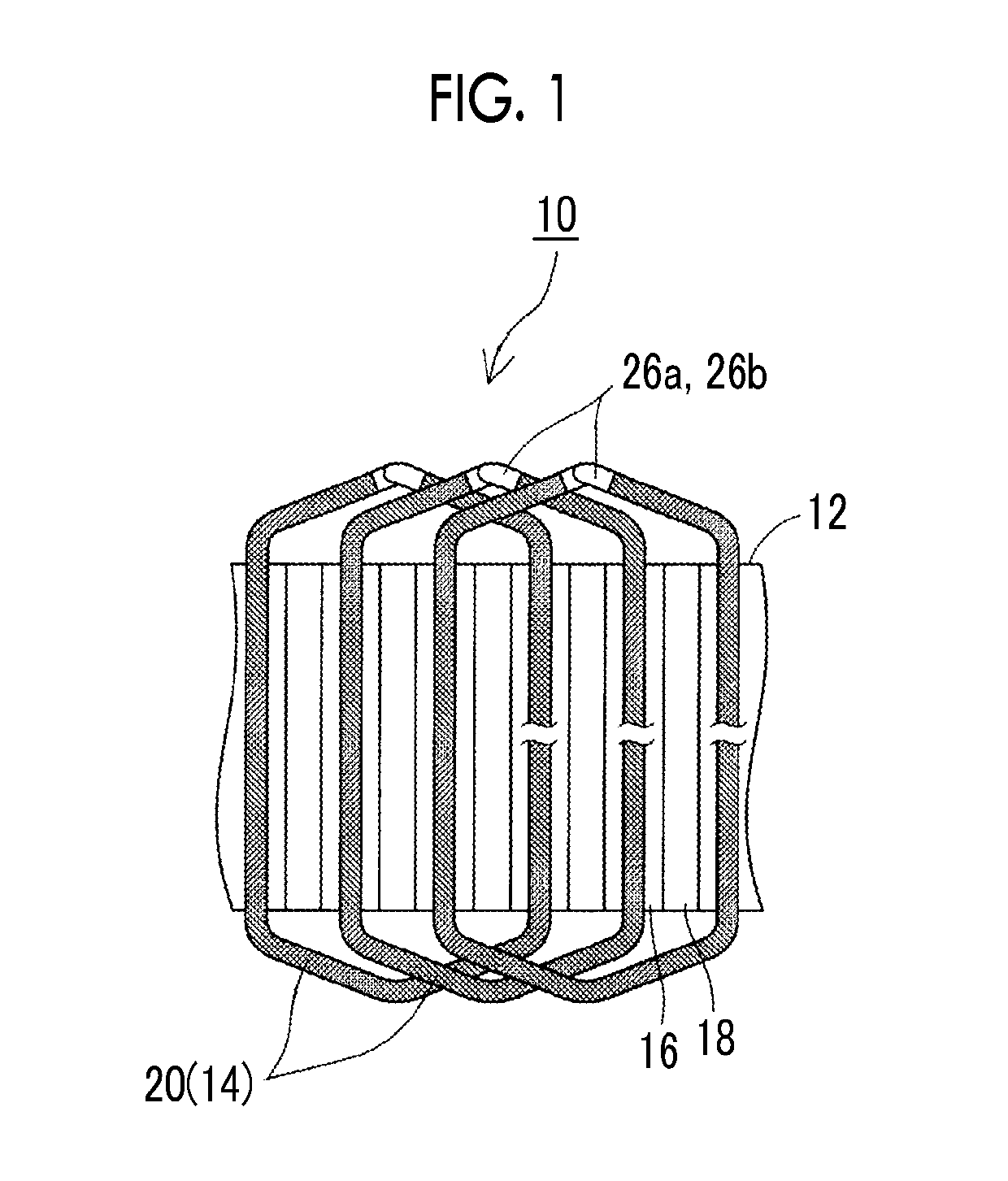
[0047]Hereinafter the configuration of a stator 10 of a rotary e emir machine will be described with reference to the drawings. FIG. 1 is a partial perspective view of the stator 10 of the rotary electric machine. In the following description, a “circumferential direction”, an “axial direction”, and a “radial direction” respectively refer to a circumferential direction, an axial direction, and a radial direction of the stator 10.

[0048]The stator 10 is combined with a rotor to configure a rotary electric machine. The rotary electric machine to which the stator 10 is applied is not particularly limited and may be used as an electric motor or may be used as a power generator. For example, the stator 10 may be applied to a rotary electric machine that is mounted on an electrified vehicle and functions as an electric motor that generates power for traveling and also functions as a power generator that generates electric power with a braking force or the like.

[0049]The stator 10 has a sta...


PUM


Abstract

A stator includes a stator core, and a stator coil wound around the stator core. The stator coil includes a firm segment coil and a second segment coil. A first peeled portion that is present in an end portion of the first segment coil is joined to a second peeled portion of the second segment coil. At least one recess portion is provided in a joining surface of the first peeled portion, which faces the second peeled portion.

Description

CROSS-REFERENCE TO RELATED APPLICATIONS[0001]This application claims priority to Japanese Patent Application No. 2017-251716 filed on Dec. 27, 2017, which is incorporated herein by reference in its entirety including the specification, drawings and abstract.BACKGROUND1. Technical Field[0002]The disclosure relates to a stator of a rotary electric machine, which includes a stator core and a stator coil wound around the stator core, and a method of manufacturing a stator coil.2. Description of Related Art[0003]In the related art, a segment conductor type stator in which a stator coil is configured by joining a plurality of segment coils to each other is known. For example, Japanese Unexamined Patent Application Publication No. 2015-201966 (JP 2015-201966 A) discloses a technique to configure a stator coil by inserting a segment coil having a U-shape into each slot of a stator core and then welding an end portion of the segment coil to an end portion of another segment coil (in the spec...

Claims


Application Information

Patent Timeline
IPC IPC(8): H02K3/12H02K15/00H02K3/38B23K35/02
CPCH02K3/12H02K15/0081H02K3/38B23K35/0255H02K3/04H02K15/04B23K26/00B23K33/00B23K26/21H02K3/28
Inventor NISHIMURA, MASAHIROMATSUMOTO, MASASHI
Owner TOYOTA JIDOSHA KK
Why Eureka
Try Eureka