Push Paddle

a push paddle and paddle technology, applied in the field of push paddles, can solve the problems of reducing the stroke rate and increasing the risk of watercraft yawing, and achieve the effects of reducing the need for buoyancy, good initial “traction”, and high drag

Inactive Publication Date: 2011-03-17
POTTER STEVEN DICKINSON
View PDF9 Cites 12 Cited by
  • Summary
  • Abstract
  • Description
  • Claims
  • Application Information

AI Technical Summary

Benefits of technology

[0044]For the push-block to exit the water quickly and cleanly, the top face of the wedge can have an angle of about 135° or more relative to the pole axis. This avoids “snagging” the water on the recoil phase of the stroke. The bottom face of the wedge is the “push” surface. An angle of 105° relative to the pole axis provides good initial “traction” (high drag) and provides lift which reduces the need for buoyancy. The lift effect can be enhanced by rounding the back end of the wedge. This increases the lift effect as the push-block goes underwater, making the push-block stay at or near the surface of the water over a wider range of pole

Problems solved by technology

A larger bottom face on the push-block with provide higher fluid drag, and less slippage, but will al

Method used


Image

  • Push Paddle
  • Push Paddle
  • Push Paddle

Examples


Embodiment Construction

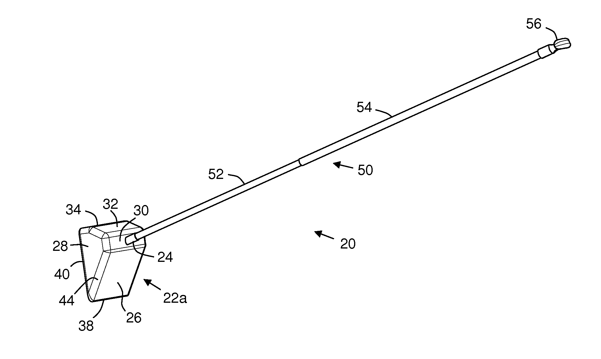
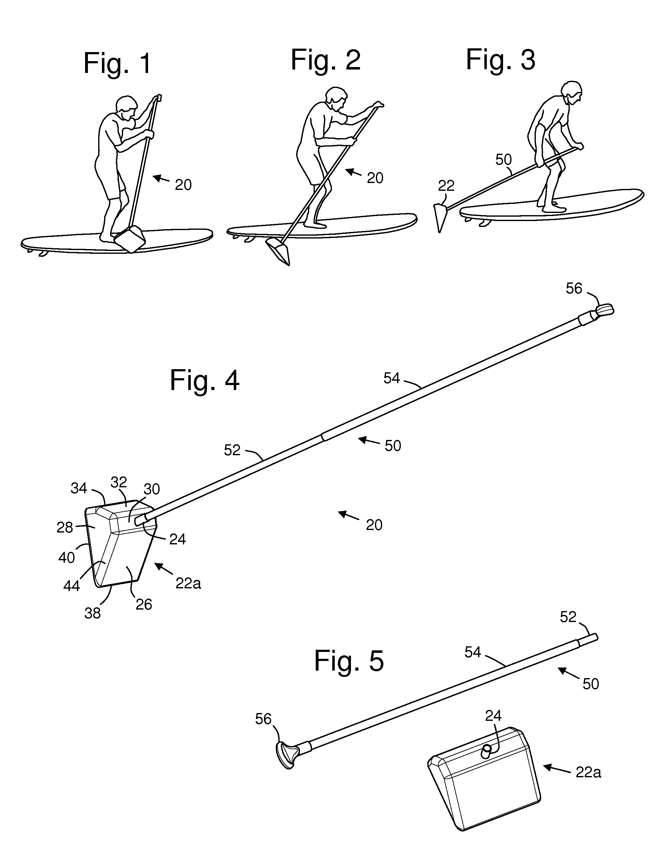
[0065]FIGS. 1-3 show push-paddle 20 being used to propel a surfboard. Push-paddle 20 comprises pole 50 and push-block 22. The user holds the upper section of the pole, and the bottom end is attached to the push-block 22. In FIG. 1, the user is about to press the push-block 22 down into the water to start the power stroke. In FIG. 2, the push-paddle is in the middle of the power-stroke and the user is applying force mostly in line with the pole axis. In this embodiment of the invention, as shown in FIG. 2, the push-block 22 is slightly underwater. In FIG. 3 the power stroke is complete and the push-block 22 is starting to emerge from the water aided by its buoyancy.

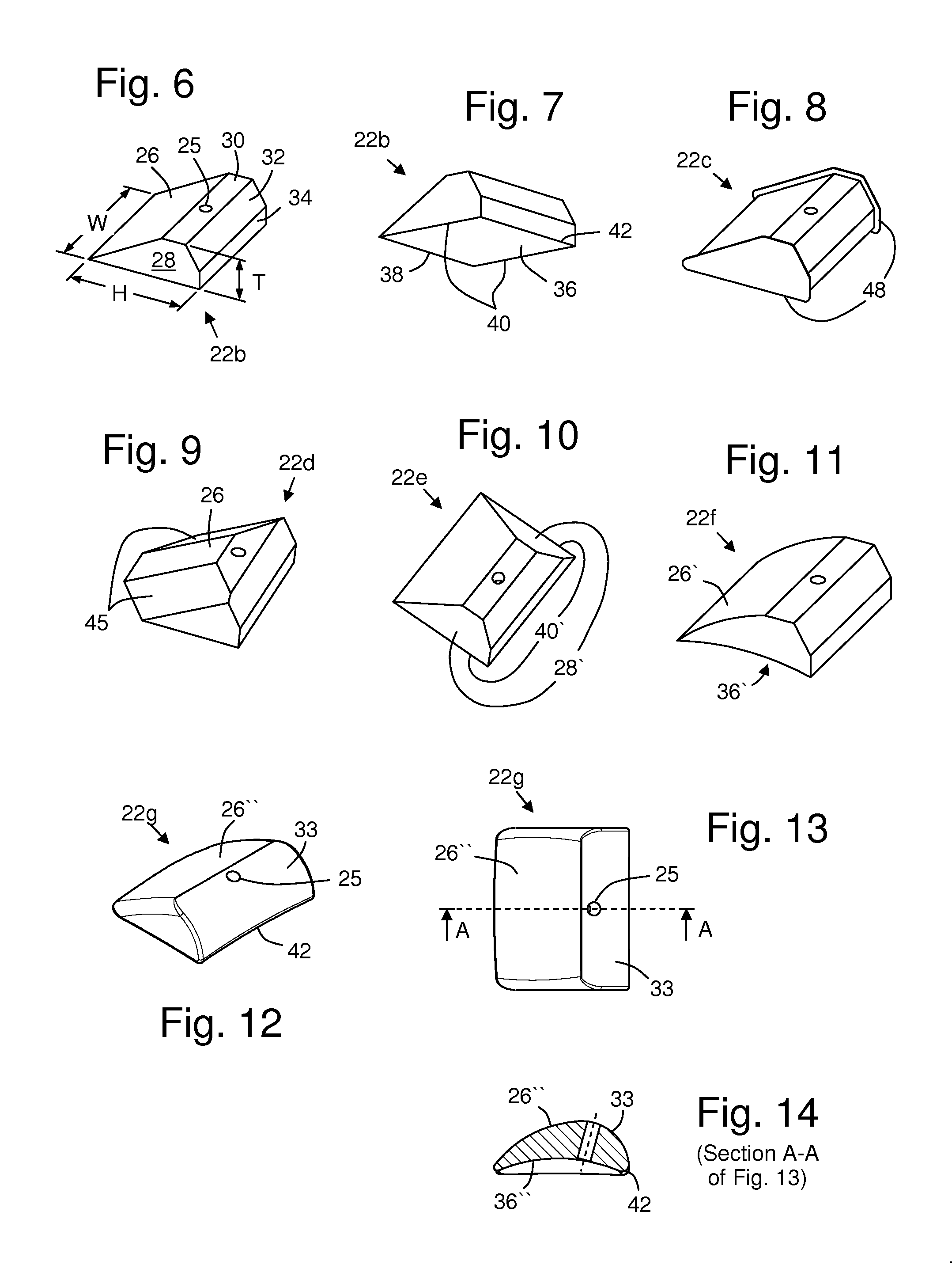
[0066]FIG. 4 shows a perspective view of push-paddle 20 with additional details. Push-block 22a is wedge-shaped. The top face 26 of the wedge, and bottom face 36 (not visible) intersect to form wedge-edge 38. Sidewalls 28 intersect the bottom face to form side edges 40, and intersect the top surface 26 to form top edges 44...


PUM


Abstract

A push-paddle has a buoyant wedge-shaped push-block attached to the bottom end of a pole. When pressed into the water wedge-end first, the push-block provides high drag and buoyant force for the user to push against and propel a watercraft using a punting-like motion. At the end of the power stroke, the wedge slips easily and quickly up out of the water allowing the user to recoil the push-paddle through the air.

Description

CROSS-REFERENCE TO RELATED APPLICATIONS[0001]This application claims the benefit of U.S. Provisional Application No. 61 / 224,035 filed Jul. 8, 2009.STATEMENT REGARDING FEDERALLY SPONSORED RESEARCH OR DEVELOPMENT[0002]Not ApplicableREFERENCE TO SEQUENCE LISTING, A TABLE, OR A COMPUTER PROGRAM LISTING COMPACT DISK APPENDIX[0003]Not ApplicableBACKGROUND OF THE INVENTION[0004]The present invention relates to poles and paddles used for propelling a boat or other watercraft from a standing position. The invention is especially relevant to stand-up paddleboarding (SUP).[0005]Examples of stand-up propulsion methods include long-handled versions of canoe and kayak paddles, punting poles for pushing off the bottom, and various types of ski-poles. The most popular paddle design for stand-up paddleboarding (SUP) is an elongated version of a canoe paddle, e.g. those made by C4 Waterman Inc. Very long kayak paddles have also been used by SUP enthusiasts as well as stand-up kayakers.[0006]Paddling ...

Claims


Application Information

Patent Timeline
IPC IPC(8): B63H16/04
CPCB63H16/04B63B34/565
Inventor POTTER, STEVEN DICKINSON
Owner POTTER STEVEN DICKINSON
Why Eureka
Try Eureka