Silent chain

a technology of silent chain and elongation, which is applied in the direction of driving chains, belts/chains/gearrings, chain elements, etc., can solve the problems of prolonging reducing the sound of hitting, so as to suppress the wear elongation of the chain, prolong the useful life of the chain, and reduce the sound of hitting

Active Publication Date: 2011-03-17
TSUBAKIMOTO CHAIN CO
View PDF26 Cites 9 Cited by
  • Summary
  • Abstract
  • Description
  • Claims
  • Application Information

AI Technical Summary

Benefits of technology

[0015]One advantage of the elongated pin hole configuration is that, if the link row plates and guide row plates move in the longitudinal direction of the chain when their teeth begin to engage sprocket teeth, the reactive force that would otherwise be received from adjoining plates is alleviated or eliminated. As a result, hitting sounds are reduced, and the alleviation of repetitive loads prolongs the useful life of the chain.
[0016]The elongated pin holes provide gaps between the edges of the pin holes and the rocker pins, which hold sufficient oil to suppress wear elongation of the chain. Suppression of wear elongation also contributes to the prolongation of the useful life of the chain.
[0017]In an embodiment of the silent chain transmission, the pin holes of the guide row plates and the link row plates can be joined, forming a single elongated opening in each of said plates. The provision of one long pin hole in each plate simplifies the manufacturing process.
[0018]In another embodiment of the silent chain transmission, each pin hole in each link row plate and each guide row plate has an elongated portion defined by an inner edge on the side of the elongated portion nearest the teeth of the plate and an outer edge on the side of the elongated portion farthest from the teeth of the plate. The outer edge is substantially straight, and configured so that, when the plate is seated on the sprocket, said outer edge is parallel to a tangent to a circle circumscribed about the tips of the sprocket teeth at the tip of the adjacent sprocket tooth on which said plate is seated. The outer edge of the pin hole therefore extends in the direction of a preceding plate seated on the sprocket. Accordingly, it is possible to alleviate or eliminate the reactive force otherwise received from the adjoining plates more steadily, to achieve a further reduction in hitting sounds, to improve the avoidance of repetitive loads otherwise applied to the rocker pins and pin holes, and to achieve still greater prolongation of the life of the chain.
[0019]In still another embodiment, the amount by which each pin hole is elongated is greater than the longest distance between successive toothed plates in the chain. The range of movement of the link row plates and guide row plates in the longitudinal direction is thereby expanded to correspond to the gaps between the ends of the plates, which limit the relative longitudinal movement of the plates of the chain. This relationship between the elongation of the pin holes and the gaps between successive plates also contributes to the steady alleviation or elimination of the reactive force otherwise received from the adjoining plates in chains of any engagement types, and to the reduction in hitting sounds, avoidance of repetitive loads, and prolongation of the life of the chain.
[0020]In still another embodiment, at least one of the rocker pins of each set is bent in a curve, whereby the distance between the rocker pins of each set varies along their lengths. The curvature of the rocker pin or pins applies a force that contracts the overall length of the chain. Accordingly, it is possible to reduce vibration that would otherwise occur due to the looseness on the slack side of the silent chain in the silent chain transmission. The curvature of the pins also contributes to the reduction of impact sounds that would otherwise be generated at the beginning the engagement of the slack side of the chain with a driven sprocket side. Finally, the curvature of the pin or pins also contributes to alleviation of repetitive loads on the rocker pins and pin holes, and to the prolongation of the useful life of the chain.

Problems solved by technology

As a result, hitting sounds are reduced, and the alleviation of repetitive loads prolongs the useful life of the chain.

Method used


Image

  • Silent chain
  • Silent chain
  • Silent chain

Examples


first embodiment

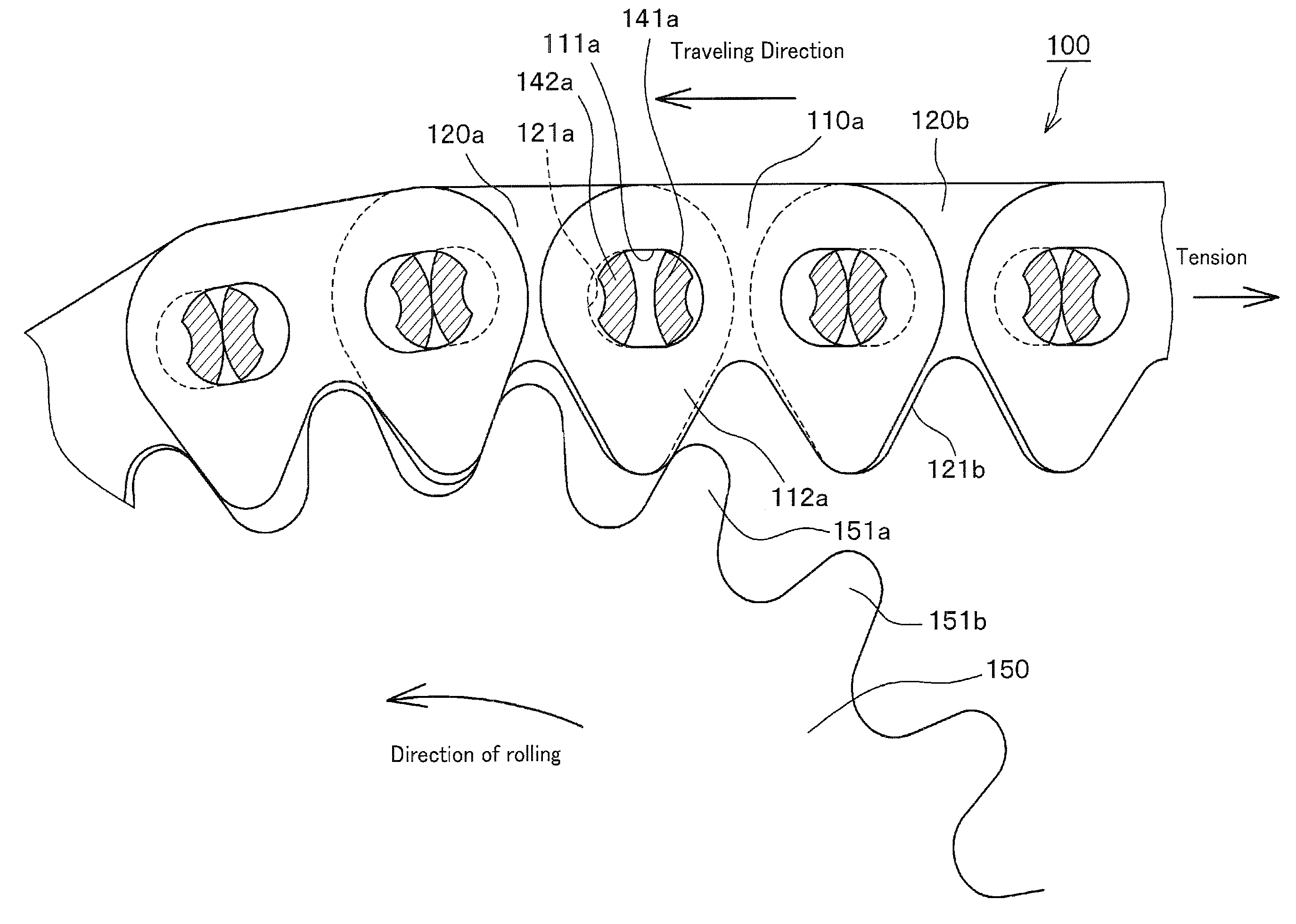
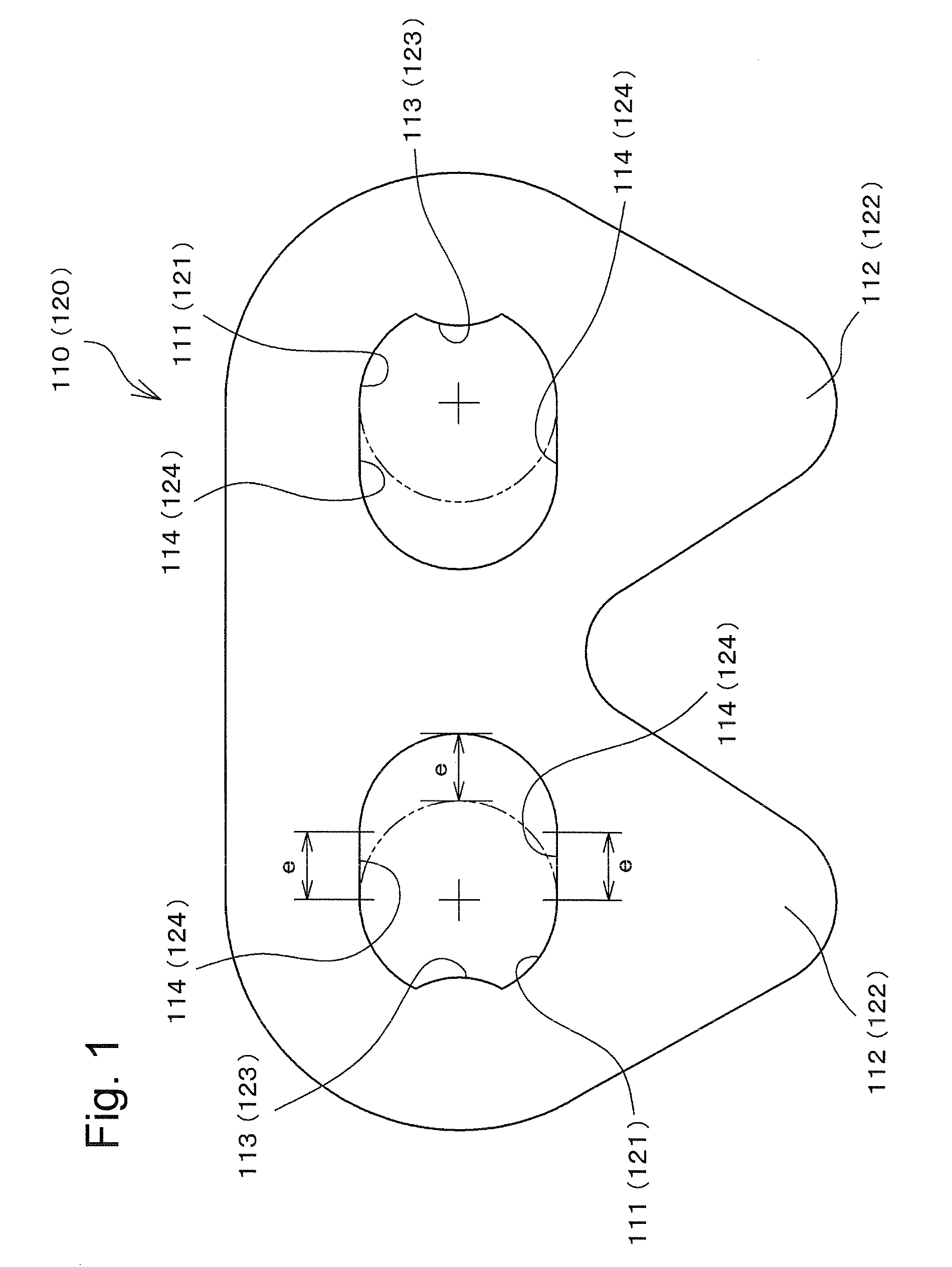
[0034]As shown in FIGS. 1 through 5, in a first embodiment, a silent chain 100 is constructed by connecting plates 110 arrayed in link rows JL, and plates 120 arrayed in guide rows GL, in interleaved relationship by inserting rocker pins 141 and 142 respectively into pin holes 111 and 121, with their convex rocking surfaces facing each other.

[0035]As shown in FIG. 1, each of the link row plates 110 has a pair of pin holes 111, and is bifurcated to form a pair of teeth 112. Each of the guide row plates 120 similarly has a pair of pin holes 121, and is bifurcated to form a pair of teeth 122. The pin holes 111 and 121 in each plate are elongated toward the center of the plate, i.e., in an inward direction from the forward and back ends of the plate, and have long side edges 114 and 124 extending generally in the direction of elongation of the chain.

[0036]The pin holes 111 and 121 are also provided with convex portions 113 and 123 at their outer sides. These convex portions engage corre...

third embodiment

[0049]In a third embodiment, shown in FIG. 7, link row plates and guide row plates 310 and 320 have pin holes with long upper side portions 314a and 324a, i.e., substantially straight side edges that are farthest from the teeth 312 (322). These side edges 314a and 324a are configured so that, when the plate is seated on sprocket 150, they are substantially parallel to a line S1 tangent to a circle circumscribing the tips of the sprocket teeth at the tip of the adjacent sprocket tooth 151b, on which the plate 310 or 320 is seated. Tooth 151b is the sprocket tooth situated between the front tooth of the plate having the upper side portion 314a or 324a and the rear tooth of a preceding plate aligned therewith along the longitudinal direction of the chain. Thus, sprocket tooth 151b is situated between, and engaged by, a front tooth of a plate in a link row or a guide row and the rear tooth of a preceding link plate in the same kind of row. As shown in the enlarged auxiliary view in FIG....


PUM


Abstract

In a chain transmission incorporating a silent chain engaged with a sprocket, the plates of the chain are connected by sets of rocker pins extending through pin holes in the plates. The pin holes are elongated toward the center of each plate, and the elongation of each pin hole is greater than the maximum amount by which the distance between points on the respective rocker pins of each set increases when said chain is inflected to the maximum extent permitted by the sprocket in a portion of the chain in seating engagement with said sprocket.

Description

CROSS REFERENCE TO RELATED APPLICATIONS[0001]This application claims priority on the basis of Japanese Patent Application No. 2009-215709, filed on Sep. 17, 2009. The disclosure of Japanese Patent Application No. 2009-215709 is incorporated by reference in its entirety.FIELD OF THE INVENTION[0002]This invention relates to a silent chain for use as a timing chain in an internal combustion engine or for power transmission in various kinds of machinery. The invention relates more specifically to a silent chain arranged to reduce or avoid hitting sounds generated when teeth on the plates of the chain first come into contact with sprocket teeth as the chain moves into engagement with a sprocket.BACKGROUND OF THE INVENTION[0003]In general, a silent chain is composed of a plurality of guide row plates, sometimes referred to as “middle” plates and link row plates, sometimes referred to as “inner” plates. In most silent chains, each such plate has a pair of pin holes and a pair of teeth. The...

Claims


Application Information

Patent Timeline
Patent Type & Authority Applications(United States)
IPC IPC(8): F16G13/06
CPCF16G13/08F16G13/04
Inventor ADACHI, SHOUHEIMORIMOTO, TAKAYUKI
Owner TSUBAKIMOTO CHAIN CO
Why Eureka
Try Eureka