

Hand Held Refrigeration Gauge
a technology of refrigeration gauge and hand held, which is applied in the direction of fluid pressure measurement by mechanical elements, refrigeration components, volume flow measurement devices, etc., can solve the problems of large temperature and pressure drop, not all the necessary features for accurate subcooling and superheat determination, and the gauge disclosed does not provide a user interfa
- Summary
- Abstract
- Description
- Claims
- Application Information
AI Technical Summary
Benefits of technology
Problems solved by technology
Method used
Image

Examples
Embodiment Construction
[0022]While this invention is susceptible of embodiment in many different forms, there are shown in the drawings, and will be described herein in detail, specific embodiments thereof with the understanding that the present disclosure is to be considered as an exemplification of the principles of the invention and is not intended to limit the invention to the specific embodiments illustrated.
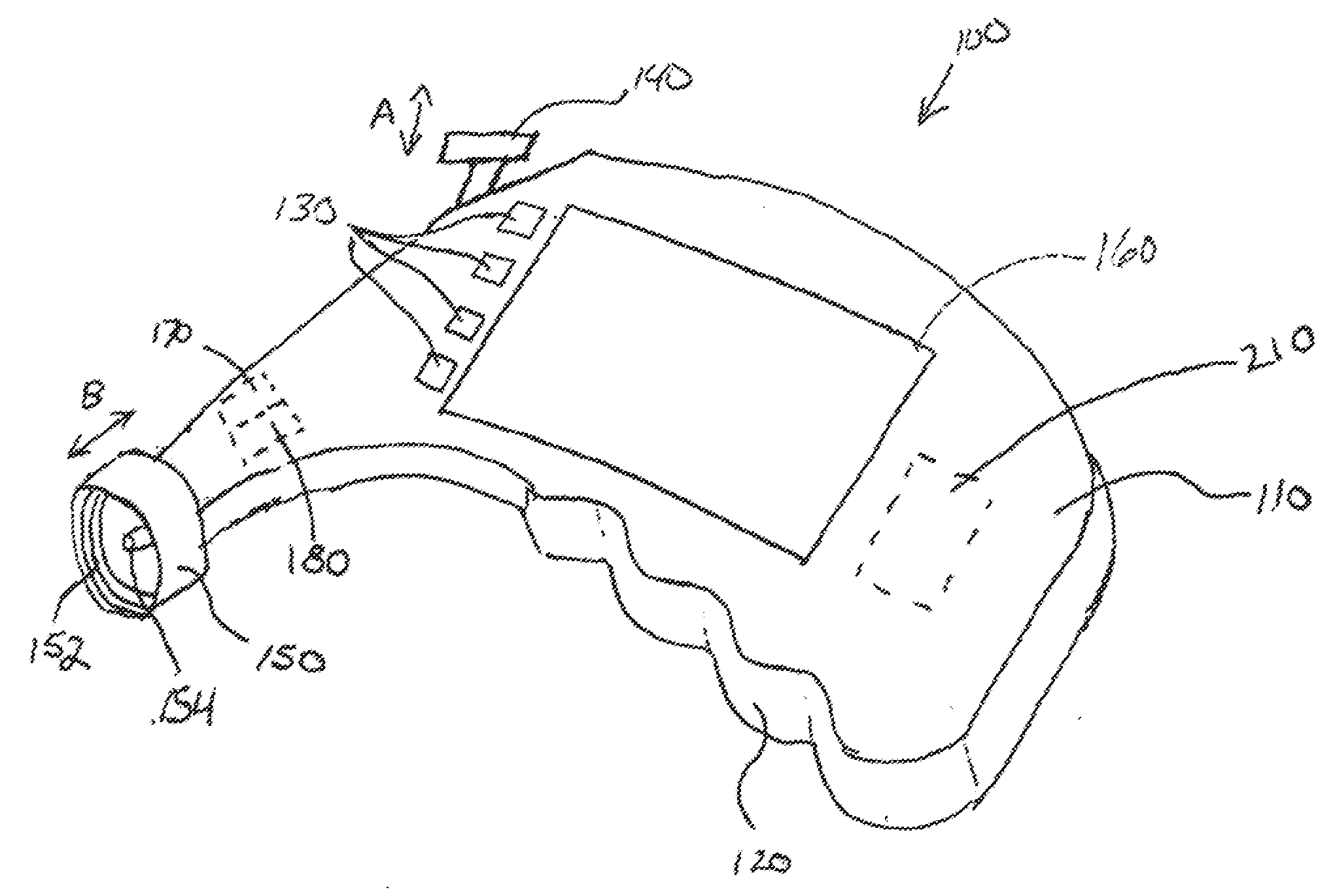
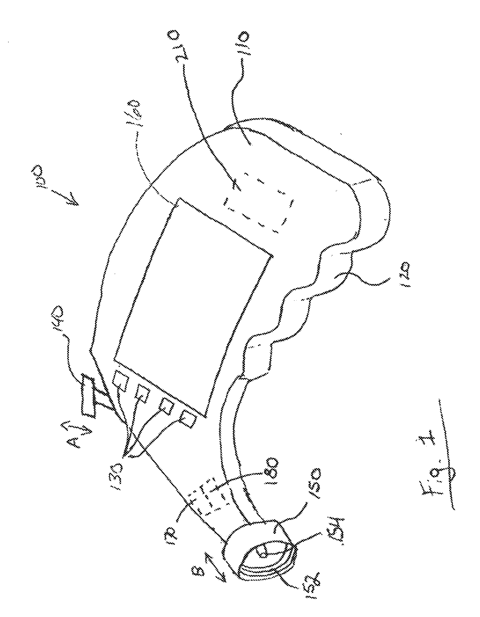
[0023]FIG. 1 shows the preferred embodiment of the hand held refrigeration gauge 100 of the present invention. The gauge has a body 110, a digital display screen 160, function buttons 130, a read button 140, a hand grip 120, and a service port connector 150.
[0024]The service port connector 150 is for engaging a service port of a refrigeration or air conditioning system. In operation, the service port connector 150 is fitted onto the service port of a refrigeration or air conditioning system to be measured so as to guide the refrigerant pressure and / or temperature from the service port into the ga...
PUM
| Property | Measurement | Unit |
|---|---|---|
| pressure | aaaaa | aaaaa |
| temperature | aaaaa | aaaaa |
| saturation temperature | aaaaa | aaaaa |
Abstract
Description
Claims
Application Information