Thermal exchanging device

Inactive Publication Date: 2011-03-24
DELTA ELECTRONICS INC
View PDF15 Cites 10 Cited by
  • Summary
  • Abstract
  • Description
  • Claims
  • Application Information

AI Technical Summary

Benefits of technology

[0008]The present invention overcomes the aforementioned disadvantages by offering a magnetically drive

Problems solved by technology

On the other hand, when the MCM is demagnetized, the magnetic moment of the MCM becomes randomized causing a disorder of the atoms to thereby absorb heat from outside of the

Method used


Image

  • Thermal exchanging device
  • Thermal exchanging device
  • Thermal exchanging device

Examples


Embodiment Construction

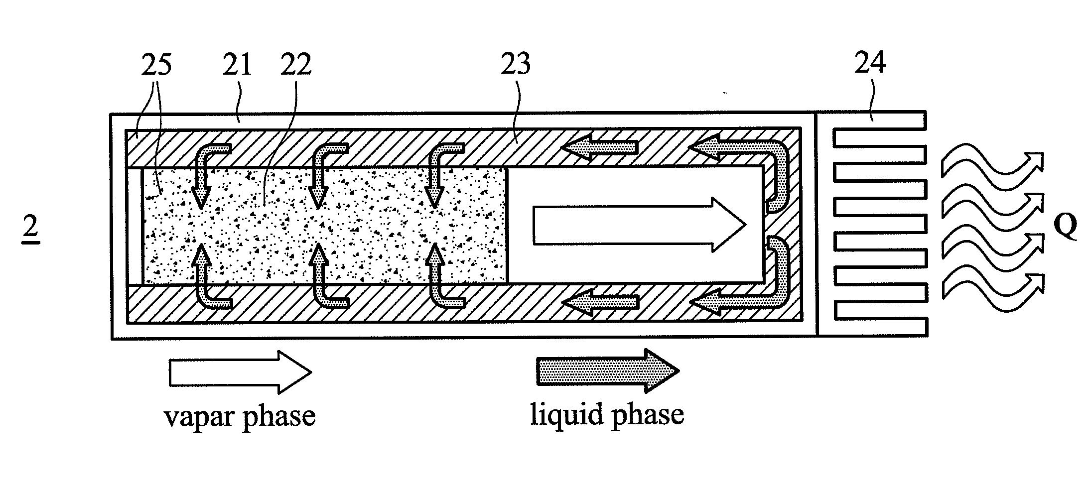
[0018]Referring to FIG. 2a, FIG. 2b, and FIG. 3, the first preferred embodiment of a thermal exchanging device of the present invention can operate with an external heat source for performing a heat exchange therebetween. As shown in FIG. 3, the thermal exchanging device 2 includes a magnetic-generating source 26, a vacuum chamber 21, a magnetically excited working material 22, a working fluid 25, a heating unit 24, a wick structure 23, and a thermal controlling unit 27. The external heat source Q has hot and cold sources Q1, Q2, in which the hot heat source Q1, for example, has a temperature that is higher than the Curie temperature of the working material 22 and the cold heat source Q2, for example, has a temperature that is lower than the Curie temperature of the working material 22. The working material 22 is excited by the magnetic-generating source 26 to thereby create a thermal flux in the chamber 21. The working fluid 25 is provided in the chamber 21 so as to communicate wit...


PUM


Abstract

A thermal exchanging device is provided to exchange heat with a hot heat source and a cold heat source. The thermal exchanging device includes a vacuum chamber, a working material capable of being excited magnetically, and a working fluid capable of undergoing a transition between two phase flows of liquid and vapor. The working fluid is provided in the chamber to communicate with the working material. When the working material is magnetically excited, the working fluid is configured to exchange heat with the cold heat source. Otherwise, the working fluid is configured to absorb heat from the hot heat source.

Description

CROSS REFERENCE TO RELATED APPLICATIONS[0001]This Application claims priority from U.S. provisional application No. 61 / 245,441, filed on Sep. 24, 2009, the entirety of which is incorporated by reference herein.BACKGROUND[0002]1. Field of the Invention[0003]The present invention is in the technical field of a thermal exchanging device, more particularly to a magnetically driven thermal exchanging device utilizing a magneto-caloric material (MCM) to generate a two-phase flow of liquid and vapor by means of magnetization and demagnetization mechanism.[0004]2. Description of the Related Art[0005]A conventional thermal exchanging device that utilizes the magneto-calorific properties of certain materials, such as Gadolinium or certain alloys, has the particularity of heating up when a magnetic field is applied (magnetization process) and of cooling to a temperature lower than the initial temperature following the diminishing effect of the magnetic field (demagnetization process). For inst...

Claims


Application Information

Patent Timeline
IPC IPC(8): F25B21/00F28D15/00
CPCF24J3/00F28D15/06F28D15/04F28D15/02F24V99/00
Inventor CHANG, SHAO-HSIUNG
Owner DELTA ELECTRONICS INC
Why Eureka
Try Eureka