Gas circulation engine

Inactive Publication Date: 2011-03-24
TOYOTA JIDOSHA KK
View PDF7 Cites 11 Cited by
  • Summary
  • Abstract
  • Description
  • Claims
  • Application Information

AI Technical Summary

Benefits of technology

[0018]The gas circulation engine according to the second aspect of the invention may further include: a bled-off oxidant supply valve that permits or shuts off communication between the oxidant bleed-off tank and an intake passage; and a bled-off oxidant control unit that permits communication between the oxidant bleed-off tank and the intake passage by opening the bled-off oxidant supply valve after the engine is restarted. The communication between the oxidant bleed-off tank and the intake passage is shut off when the engine is stopped. With the structure described above, the bled-off oxidant is supplied to the intake passage and burned in the combustion chamber. Therefore,

Problems solved by technology

This may cause some inconveniences, for exampl

Method used


Image

  • Gas circulation engine
  • Gas circulation engine
  • Gas circulation engine

Examples


Example

[0028]Hereafter, a working gas circulation engine according to a first embodiment of the invention will be described with reference to FIGS. 1 to 4.

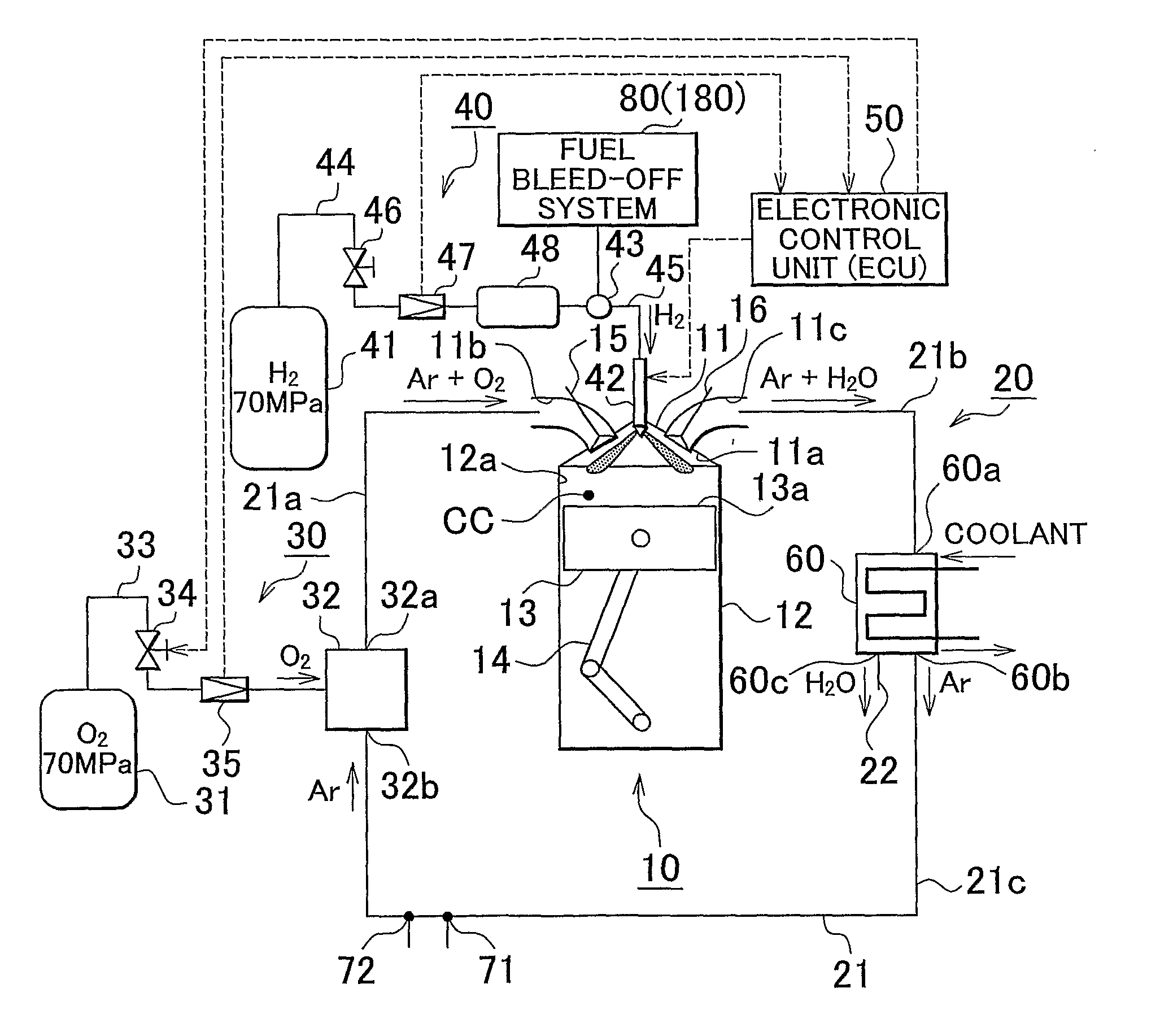
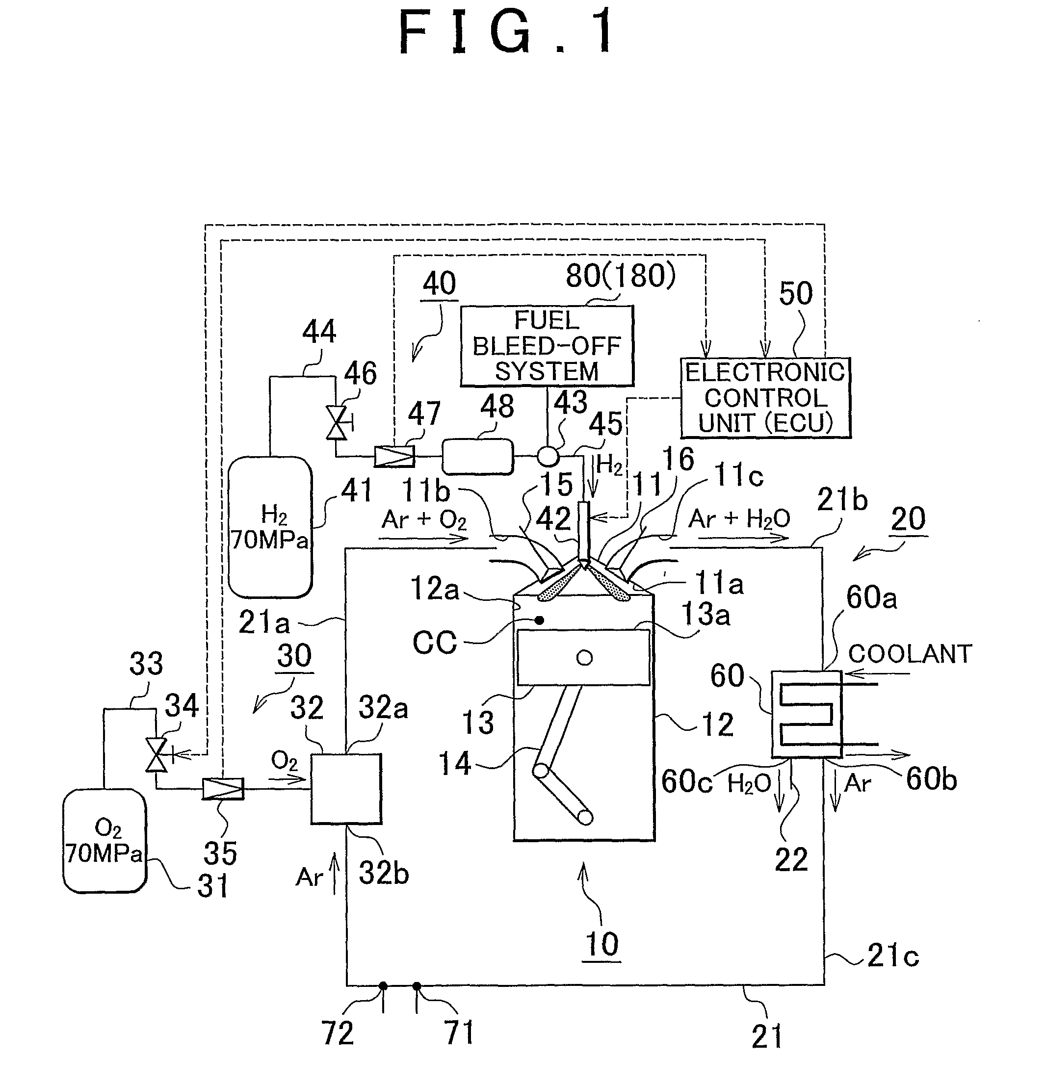
[0029]The working gas circulation engine according to the first embodiment of the invention is a so-called closed-cycle engine that has a combustion chamber which is supplied with an oxidant, fuel, the combustion (oxidation) of which is promoted by the oxidant, and working gas that generates power with the use of combustion of the fuel, and a circulation path which connects an intake-side portion and an exhaust-side portion of the combustion chamber to each other, and that is formed in such a manner that the working gas is circulated back to the combustion chamber through the circulation path without being released into the atmosphere. In the working gas circulation engine, the fuel is burned in the combustion chamber, whereby the working gas is thermally expanded to generate power.

[0030]First, the structure of the working gas circulatio...

Example

[0098]Next, a working gas circulation engine according to a second embodiment of the invention will be described with reference to FIGS. 5 and 6.

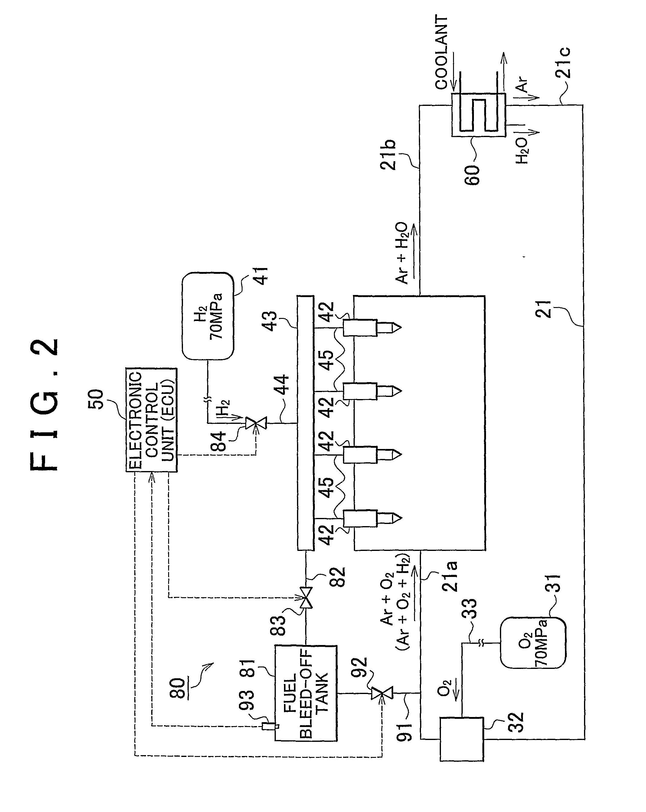
[0099]The working gas circulation engine according to the second embodiment of the invention is the same as the working gas circulation engine according to the first embodiment except that a fuel bleed-off system 180 is used instead of the fuel bleed-off system 80.

[0100]The fuel bleed-off system 80 according to the first embodiment of the invention bleeds the fuel in the first high-pressure fuel supply passage 43 off into the fuel bleed-off tank 81 using the difference between the pressure in the first high-pressure fuel supply passage 43 and the pressure in the fuel bleed-off tank 81. Therefore, when the pressure in the fuel bleed-off tank 81 is too high, the fuel is not bled off into the fuel bleed-off tank 81, which makes it difficult to decrease the pressure in the first high-pressure fuel supply passage 43.

[0101]Therefore, according to...


PUM


Abstract

A gas circulation engine includes a combustion chamber to which high-pressure fuel in a first high-pressure fuel supply passage, an oxidant and working gas are supplied; a circulation path that connects an intake-side portion and an exhaust-side portion of the combustion chamber to each other; a fuel bleed-off tank into which the high-pressure fuel in the first high-pressure fuel supply passage is bled off; a fuel bleed-off valve that permits or shuts off communication between the first high-pressure fuel supply passage and the fuel bleed-off tank; and a fuel bleed-off control unit that permits communication between the first high-pressure fuel supply passage and the fuel bleed-off tank by opening the fuel bleed-off valve when the engine is stopped, the communication between the first high-pressure fuel supply passage and the fuel bleed-off tank being shut off during operation of the engine.

Description

BACKGROUND OF THE INVENTION[0001]1. Field of the Invention[0002]The invention relates generally to a gas circulation engine that has a combustion chamber and a circulation path that connects an intake-side portion and an exhaust-side portion of the combustion chamber to each other. More specifically, the invention relates to a working gas circulation engine that has a combustion chamber which is supplied with an oxidant, fuel, the combustion (oxidation) of which is promoted by the oxidant, and working gas that generates power with the use of combustion of the fuel, and a circulation path that connects an intake-side portion and an exhaust-side portion of the combustion chamber to each other, and that is formed in such a manner that the working gas is circulated back to the combustion chamber through the circulation path without being released into the atmosphere.[0003]2. Description of the Related Art[0004]Working gas circulation engines of this type are so-called closed-cycle engin...

Claims


Application Information

Patent Timeline
IPC IPC(8): F02B43/12F02M21/00F02B47/08
CPCF02B43/10F02D9/02F02D9/08F02M21/00Y02T10/32F02M25/12Y02T10/121Y02T10/14F02M25/10Y02T10/12Y02T10/30
Inventor KUROKI, RENTAROSAWADA, DAISAKUMITANI, SHINICHI
Owner TOYOTA JIDOSHA KK
Why Eureka
Try Eureka