Electrical and data outlet decommissioning arrangement

a technology for decommissioning arrangements and electrical outlets, applied in the direction of electrical apparatus casings/cabinets/drawers, electrical apparatus connections, casings/cabinets/drawers, etc., can solve the problems of electrical outlets that are dangerous for small children, and achieve the effect of simple hand pressur

Active Publication Date: 2011-03-24
PECKHAM ALBERT E
View PDF3 Cites 8 Cited by
  • Summary
  • Abstract
  • Description
  • Claims
  • Application Information

AI Technical Summary

Benefits of technology

[0021]The locking tab has a distal lower end portion with a radius of curvature thereon, to permit the locking tab to slide and deflect against the upper edge of the inner perimeter wall of the receiving baseplate using simple hand pressure and to hence slip into the locking tab receiving slot without the use of a tool. For removal of the decommissioning plate, a tool, such as a screwdriver, may be inserted into the recess between the cover plate and the inner perimeter wall at the locking tab receiving slot, to flex the locking tab inwardly and hence permit the decommissioning cover plate to be pivoted about its engagement tabs on its opposite side thereon for removal of that decommissioning cover plate from the receiving baseplate.

Problems solved by technology

Electrical outlets may be dangerous to small children when access to those electrical outlets is left available to them.
The property owner where these electrical outlets may be arranged may not wish to have these electrical outlets available for use by just anyone, such as small children, travelers or people just looking for free electricity.

Method used


Image

  • Electrical and data outlet decommissioning arrangement
  • Electrical and data outlet decommissioning arrangement
  • Electrical and data outlet decommissioning arrangement

Examples


Embodiment Construction

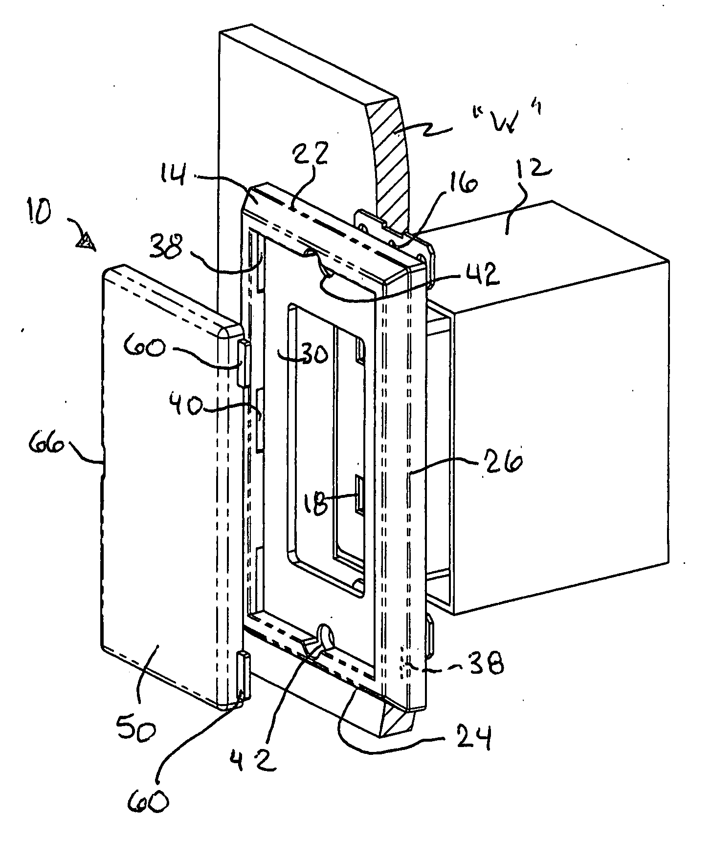
[0034]Referring now to the drawings in detail, and particularly to FIG. 1 which shows the present invention which comprises a (temporary) electrical or data outlet decommissioning arrangement 10, wherein the typical cover plate (not shown for clarity) is removed from the front of an electrical outlet box 12 in a wall “W”. A replacement receiving baseplate 14 is then attached to the front surface of the electrical outlet 18 by a pair of threaded members which extend through opposite ends of the receiving baseplate 14 and into threaded openings 16, at opposite ends of the electrical outlet 18.

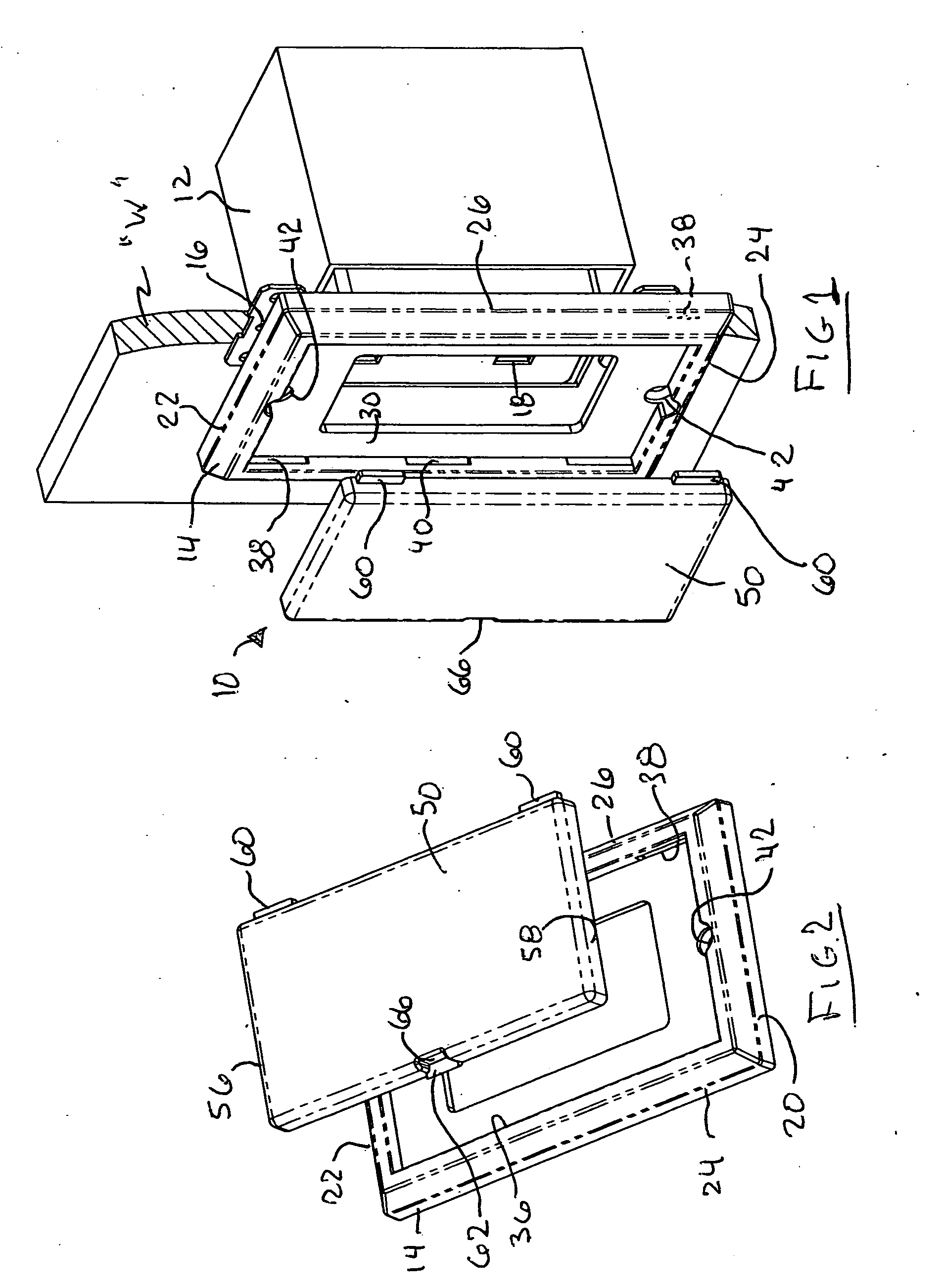
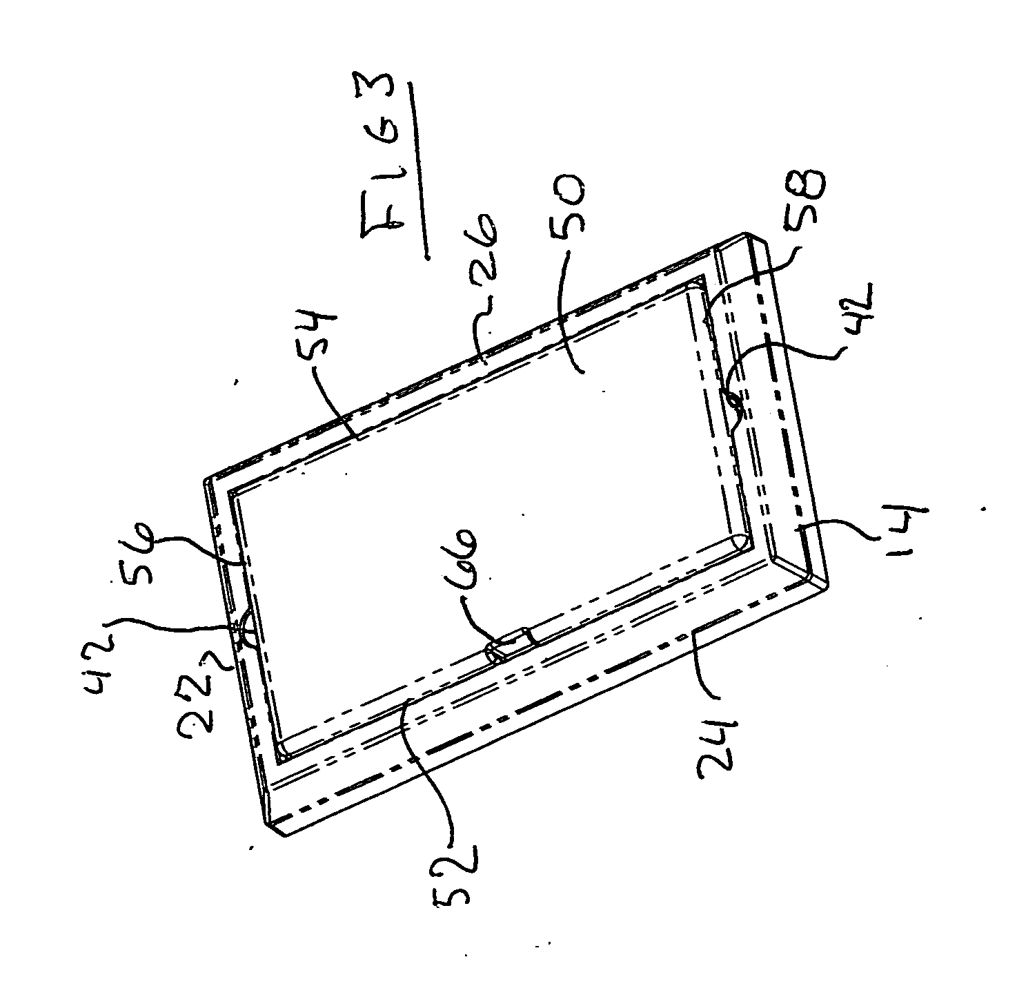
[0035]The receiving baseplate 14 is a generally rectangular unit, as shown in FIGS. 1, 2, 3 and 6, having a pair of transverse ends 20 and 22, as well as a pair of opposed parallel first and second side portions 24 and 26. An inner peripheral surface 30 extends inwardly from the transverse ends 20 and 22 and the pair of opposed parallel side portions 24 and 26 to define an internal rectangular op...


PUM


Abstract

A temporary electrical or data outlet decommissioning arrangement comprising: a generally rectangularly shaped receiving baseplate for exchange with a cover plate on an electrical outlet box; a cover plate having a plurality of receiving baseplate engagement tabs thereon, wherein the baseplate has two side walls and two transverse end walls defining a cover plate receiving opening, the side walls each have a common plurality of tab-receiving slots therein, and wherein the cover plate has two side walls and two transverse end walls, defining the shape of the cover plate to mate with the cover plate receiving opening; wherein the cover plate has a pair of engagement tabs extending off of one side wall, and has a single locking tab on the side opposite the pair of engagement tabs, and the single locking tab has an adjacent recessed support wall to provide a recess in the side wall of the cover plate to permit a tool access for removal of the cover plate from the baseplate.

Description

BACKGROUND OF THE INVENTION[0001]1. Field of the Invention[0002]This invention relates to electrical or data outlets and particularly to secure cover plate arrangements to minimize misuse of outlets.[0003]2. Prior Art[0004]Electrical outlets may be dangerous to small children when access to those electrical outlets is left available to them. Those electrical outlets may also often be available for use by the general public for the operation of their personal communication devices, laptops and various other electrical equipment. The property owner where these electrical outlets may be arranged may not wish to have these electrical outlets available for use by just anyone, such as small children, travelers or people just looking for free electricity.[0005]In many public places, electrical and / or data outlets are merely taped over rather than being electrically disconnected, removed and blanked off, probably to avoid the time and cost of an electrician and the possible future need to r...

Claims


Application Information

Patent Timeline
Patent Type & Authority Applications(United States)
IPC IPC(8): H01R13/44
CPCH01R13/447H01R2103/00H01R24/76H01R13/74
Inventor PECKHAM, ALBERT E.
Owner PECKHAM ALBERT E
Why Eureka
Try Eureka