Vehicular radar device

a radar device and vehicle technology, applied in the field of vehicle radar devices, can solve the problems of increasing unable to obtain the relative position of the peripheral target with respect to the traveling subject vehicle, etc., and achieve the effect of reducing the size of the devi

Active Publication Date: 2011-03-24
MITSUBISHI ELECTRIC CORP
View PDF10 Cites 24 Cited by
  • Summary
  • Abstract
  • Description
  • Claims
  • Application Information

AI Technical Summary

Benefits of technology

[0007]The present invention has been made in view of the above-mentioned problem, and therefore has an object to provide a vehicular radar device which is capable of reducing an operation resource quantity necessary for a process of estimating an axis deviation angle, to thereby reduce a device size.
[0009]According to the present invention, only the axis deviation angle is estimated by a simple operation with the use of an approximate expression instead of a principle expression satisfied by the axis deviation angle. This leads to advantages that the operation resource quantity necessary for the process of estimating the axis deviation angle is reduced, to thereby reduce the device size.

Problems solved by technology

With this deviation, a relative position of a peripheral target with respect to a traveling subject vehicle cannot be obtained.
However, the related art suffers from such a problem that not only the axis deviation angle ψ but also the velocity error ratio A must be estimated, and a large number of operation resources are required for an estimating process, which increases the device size, for example.

Method used


Image

  • Vehicular radar device
  • Vehicular radar device
  • Vehicular radar device

Examples


Embodiment Construction

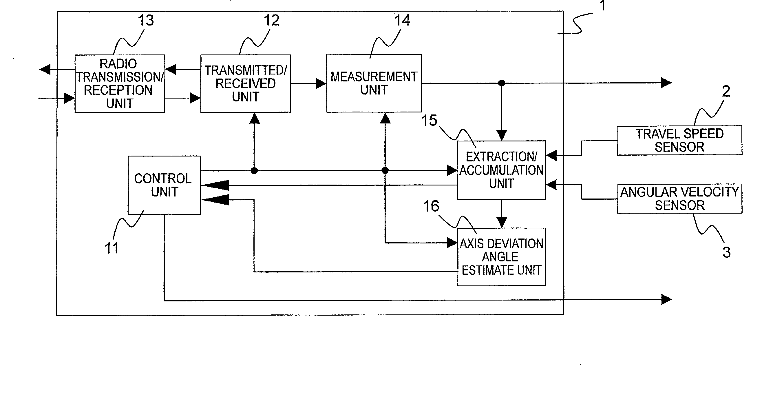
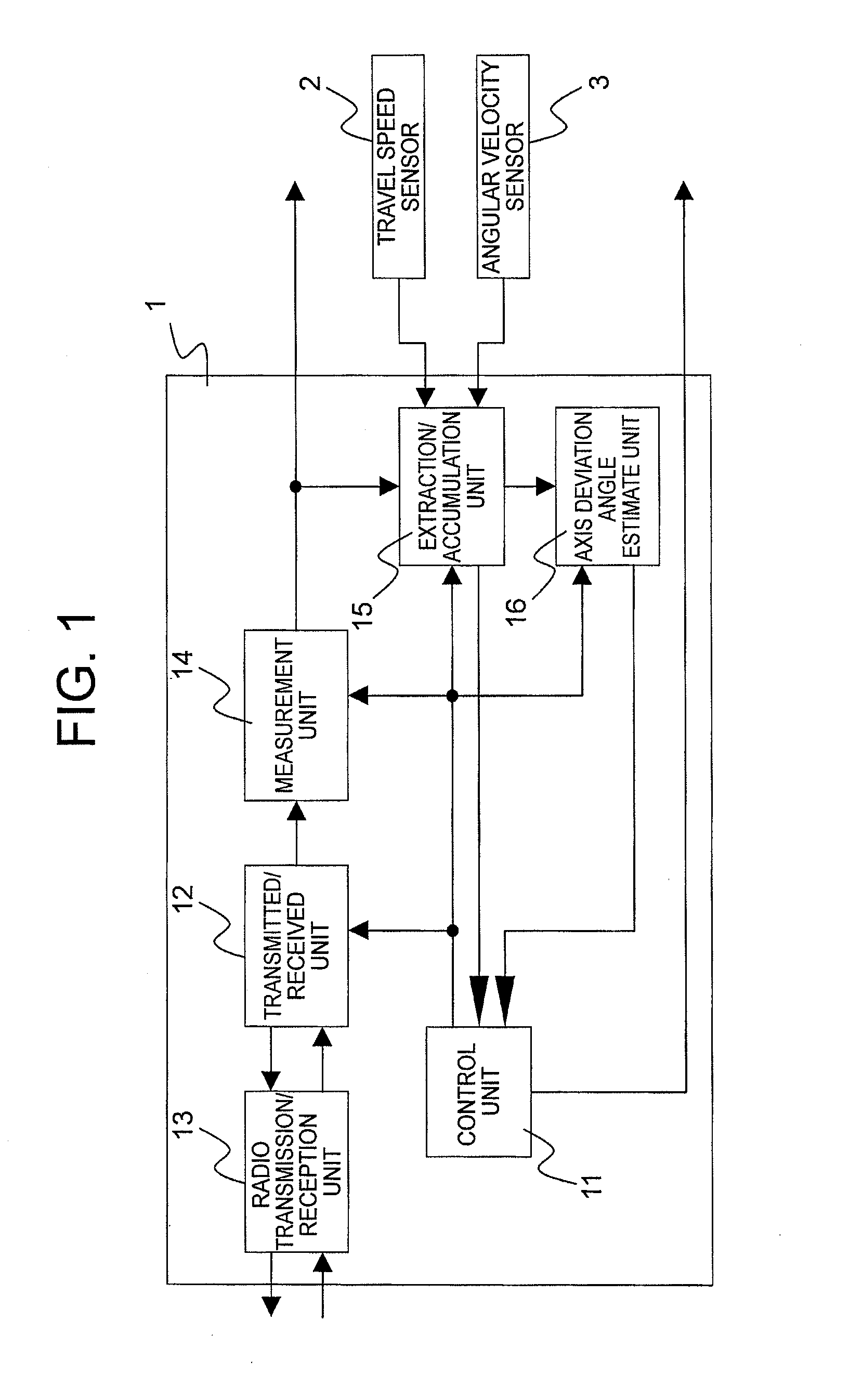
[0014]Hereinafter, an embodiment of the present invention is described in detail. FIG. 1 is a block diagram illustrating a configuration of a vehicular radar device according to the embodiment of the present invention. A vehicular radar device 1 illustrated in FIG. 1 includes a control unit 11 that controls the respective configurations of the vehicular radar device 1, a transmitted / received unit 12 that generates a transmitted signal, and converts a received electromagnetic wave into a received signal, a radio transmitted / received unit 13 that radiates the transmitted signal generated by the transmitted / received unit 12 into a space as a transmitted electromagnetic wave, and receives the electromagnetic wave reflected by a target or the like, and a measurement unit 14 that measures an azimuth angle and a relative Doppler velocity of the target as target information. The vehicular radar device 1 also includes an extraction / accumulation unit 15 that extracts target information satisf...


PUM


Abstract

Provided is a vehicular radar device which is capable of reducing an operation resource quantity necessary for a process of estimating an axis deviation angle in a radar measurement coordinate system, to thereby reduce a device size. The vehicular radar device includes: a measurement unit that measures an azimuth angle and a relative Doppler velocity; an extraction / accumulation unit that extracts target information satisfying conditions related to the relative Doppler velocity, a travel speed and a turning velocity, and accumulates the azimuth angle and a velocity ratio obtained by dividing the relative Doppler velocity by the travel speed of the subject vehicle among the extracted target information; and an axis deviation angle estimate unit that reads the target information accumulated in the extraction / accumulation unit, and estimates an axis deviation angle of the measurement coordinate system of a radar based on a second-order polynomial expression of the azimuth angle of the target.

Description

BACKGROUND OF THE INVENTION[0001]1. Field of the Invention[0002]The present invention relates to a vehicular radar device having a radar to be mounted on a vehicle, which detects an object existing in the periphery of a subject vehicle (hereinafter, referred to as “target”) and measures a position and a velocity of the target, and more particularly, to a vehicular radar device which is capable of estimating and correcting a reference axis deviation angle (hereinafter, referred to as “axis deviation angle”) of a radar measurement coordinate system.[0003]2. Description of the Related Art[0004]When the vehicular radar is mounted on a vehicle, due to various factors, a vehicle forward direction may be deviated from the reference axis of the measurement coordinate system of the radar as illustrated in axis deviation examples I and II with respect to an ideal state, as illustrated in FIG. 3. With this deviation, a relative position of a peripheral target with respect to a traveling subjec...

Claims


Application Information

Patent Timeline
Patent Type & Authority Applications(United States)
IPC IPC(8): G01S13/58G01S13/00G01S13/931
CPCG01S7/4026G01S13/52G01S13/58G01S13/931G01S2013/9375G01S2007/403G01S7/4056G01S2013/9353G01S2007/4091G01S2013/93271G01S2013/932G01S7/403G01S7/4091
Inventor MITSUMOTO, MASASHI
Owner MITSUBISHI ELECTRIC CORP
Why Eureka
Try Eureka