
Backflow prevention valve and fluid discharge device

Active Publication Date: 2011-03-24
SEIKO EPSON CORP
View PDF5 Cites 12 Cited by
  • Summary
  • Abstract
  • Description
  • Claims
  • Application Information

AI Technical Summary

Benefits of technology

[0022]With the invention described herein, fluid flowing in from the port flows along the fluid conduction channel and travels around to the opposite side of the port in the sealed area even if the port is formed at a position eccentric to the center of the area sealed by the valve plug. As a result, fluid can be made to flow to all parts of the gap between the valve plug and the valve plug seating surface and flow out in all directions, and the valve plug can be separated from the valve plug seating surface. The path resistance of the backflow prevention valve can therefore be reduced, and loss of pressure applied to fluid supply can be reduced. In addition, by flowing fluid through the fluid conduction channel to the opposite side of the port, a drop in the flow rate in areas where the port is not formed can be suppressed, and formation of bubbles can be suppressed.

Problems solved by technology

With this backflow prevention valve, however, there are situations in which ports cannot be disposed wherever desired in the sealed area that is sealed by the umbrella of the valve plug (the circular area surrounding the support orifice) due to installation space requirements.
Path resistance therefore increases and pressure loss increases.
The bubbles therefore do not flow easily, interfere with smooth fluid flow, and can adversely affect flow on the downstream side of the backflow prevention valve.

Method used


Image

  • Backflow prevention valve and fluid discharge device
  • Backflow prevention valve and fluid discharge device
  • Backflow prevention valve and fluid discharge device

Examples


Embodiment Construction

[0033]An inkjet printer and a control method therefor are described below as a preferred embodiment of a fluid discharge device according to the invention with reference to the accompanying figures.

[0034]General Configuration of an Inkjet Printer

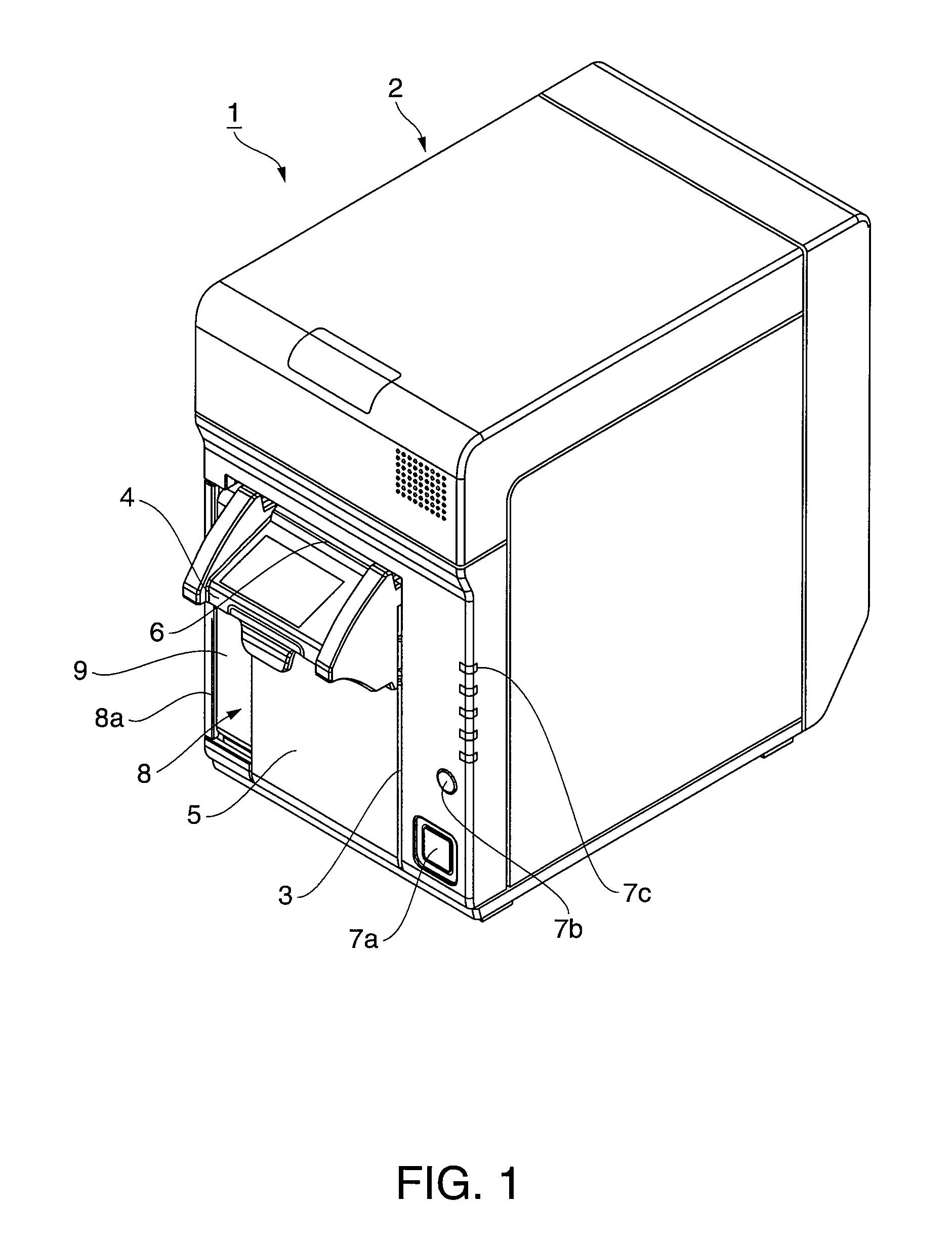
[0035]FIG. 1 is an external oblique view of an inkjet printer. The inkjet printer 1 prints in color on continuous web of recording paper delivered from a paper roll using plural different colors of ink, and has a generally box-shaped printer case 2. An opening 3 for loading roll paper is formed in the front center part of the printer case 2, and the opening 3 is closed by an access cover 5 to which a recording paper discharge guide 4 is disposed at the top. A recording paper exit 6 is formed between the recording paper discharge guide 4 and the top edge part of the opening 3 in the printer case 2. When a lock mechanism not shown is released and the recording paper discharge guide 4 is pulled forward by hand, the access cover 5 can pivot forw...


PUM


Abstract

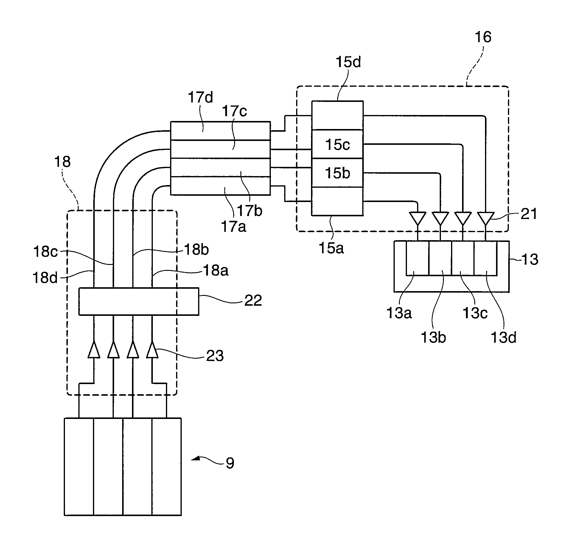
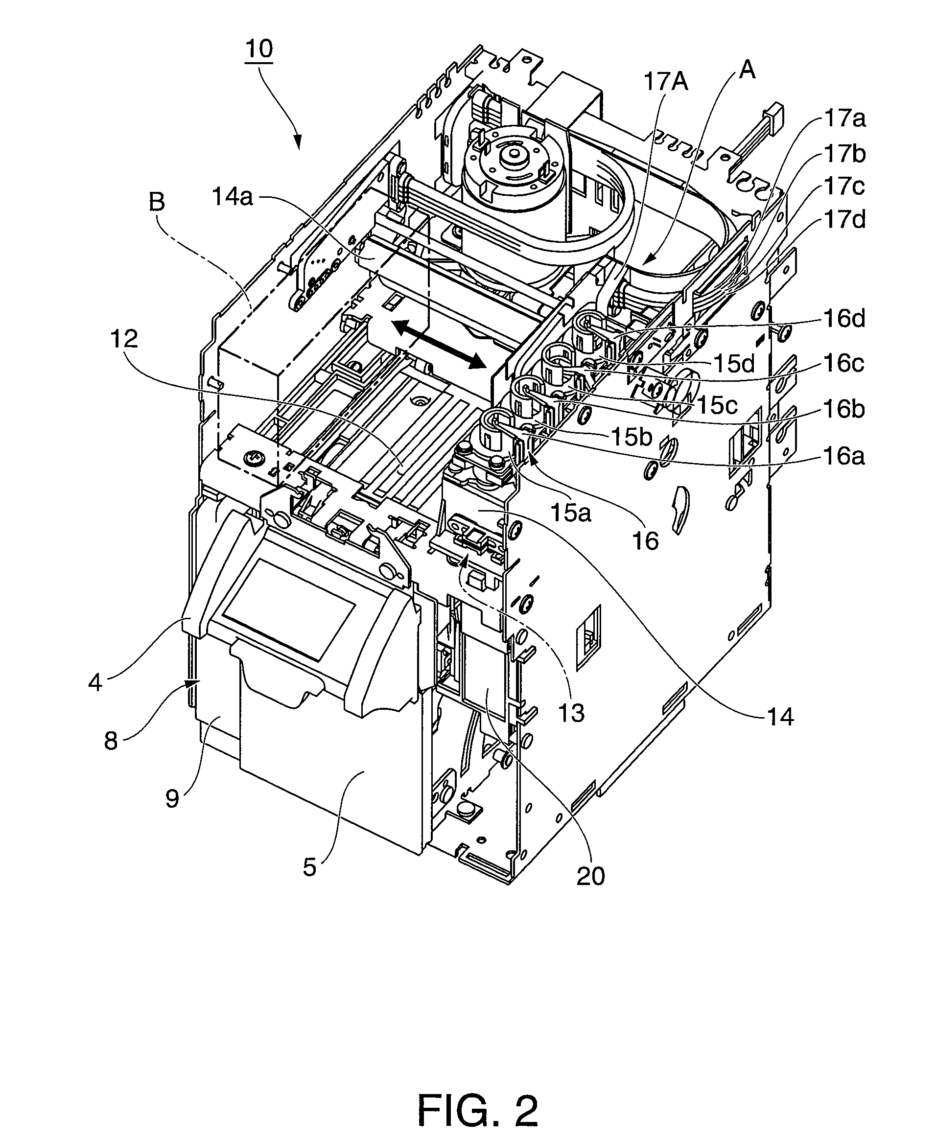
An inkjet printer has a backflow prevention valve disposed to bottom of subtanks to of the diaphragm pump unit mounted on a carriage, and causes ink passing through the backflow prevention valve to flow to the inkjet head side. A support orifice that supports an umbrella-shaped valve plug, a port formed at a position circumferentially eccentric to the center of the support orifice, and a fluid conduction channel extending from an edge of the port circumferentially around the support orifice are disposed to the valve plug seating surface of the backflow prevention valve. A discharge orifice that discharges ink to the inkjet head side is disposed in the outside wall of the valve plug seating surface, and the discharge orifice and port are formed on the same side of the center of the support orifice.

Description

BACKGROUND[0001]1. Technical Field[0002]The present invention relates to a backflow prevention valve having a valve plug disposed opposite a port formed in the valve plug seating surface, and causes the valve plug to deform elastically according to fluid pressure to open and close the port, and relates more particularly to a backflow prevention valve that can suppress an increase in path resistance and a drop in the flow rate even when the valve port is formed at an eccentric position. The invention also relates to a fluid discharge device that has this backflow prevention valve disposed in the fluid path.[0003]2. Related Art[0004]Constructions that have a support orifice supporting the valve plug and a fluid port through which fluid flows formed in the valve plug seating surface, have the valve plug disposed opposite the fluid port, and elastically deform the valve plug according to the fluid pressure from the fluid port side and the fluid pressure from the opposite side to open an...

Claims


Application Information

Patent Timeline
IPC IPC(8): B41J2/175
CPCB41J2/055B41J2/17509F16K15/148B41J2/17596B41J29/02B41J2/17553Y10T137/789
Inventor TAGA, SUSUMU
Owner SEIKO EPSON CORP
Learn More