Thermal fluid flow sensor and method of forming same technical field

a technology of temperature sensing elements and sensors, applied in the field of sensors, can solve the problems of affecting the reliability and operation life of the sensors, affecting the reliability of the sensors, and the type of sensors is expensive to make and integrate into existing sensor applications, so as to reduce the path resistance of the temperature sensing elements and the signal conditioning circuitry. , the effect of increasing the signal to noise ratio

Inactive Publication Date: 2007-08-14
HONEYWELL INT INC
View PDF6 Cites 35 Cited by
  • Summary
  • Abstract
  • Description
  • Claims
  • Application Information

AI Technical Summary

Benefits of technology

[0019]By interconnecting the temperature sensing elements directly to signal conditioning circuitry disposed on the substrate top surface, the path resistance between the temperature sensing elements and signal conditioning circuitry is significantly reduced in comparison to known flow sensors in which the signal conditioning circuitry is located remote from the sensor substrate. A decrease in the sensor path resistance between the signal conditioning circuitry and the temperature sensing elements increases the sensor signal to noise ratio which improves the sensor performance, especially for low current measurements. Also, disposing the temperature sensing heating elements on a low thermal conductivity region which is included on a silicon integrated circuit substrate in advantageous in that a more structurally robust fluid flow sensor can be mass produced by means of low cost silicon wafer level processing techniques thereby providing a low cost robust flow sensor.
[0020]The signal conditioning circuitry can comprise one or more integrated circuit elements, such as a thin film transistors, diodes and / or resistors, which can also be manufactured at low cost by means of known wafer level processing techniques further reducing the sensor manufacturing cost.

Problems solved by technology

However, a major drawback of microbridge liquid sensors is that the performance of the sensors is limited when operating in harsh environments or in high mass or high flow rate conditions.
In such conditions, particulates of the flowing gas or liquid being measured are easily deposited in the underlying structure of the microbridge causing uncontrolled thermal changes and even damage to the sensor so that the reliability and operating life time of the sensors can be adversely affected.
Although this type of microstructure sensor is capable of reliable and rapid-response operation under harsh environments making it a versatile fluid flow sensor for a variety of applications, this type of sensor is expensive to make and integrate into existing sensor applications.

Method used


Image

  • Thermal fluid flow sensor and method of forming same technical field
  • Thermal fluid flow sensor and method of forming same technical field
  • Thermal fluid flow sensor and method of forming same technical field

Examples


Embodiment Construction

[0033]The particular values and configurations discussed in these non-limiting examples can be varied and are cited merely to illustrate at least one embodiment of the present invention and are not intended to limit the scope of the invention.

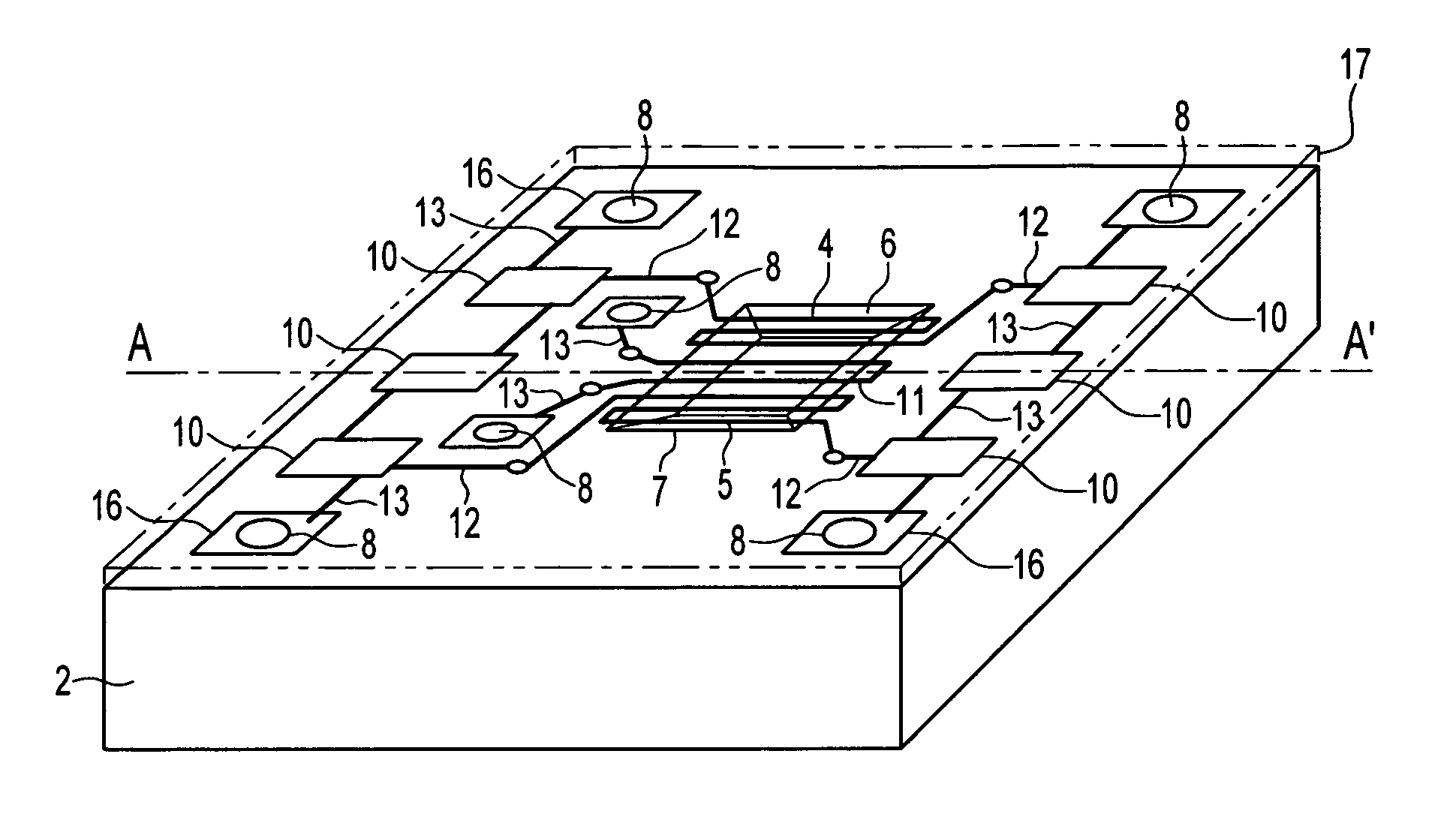
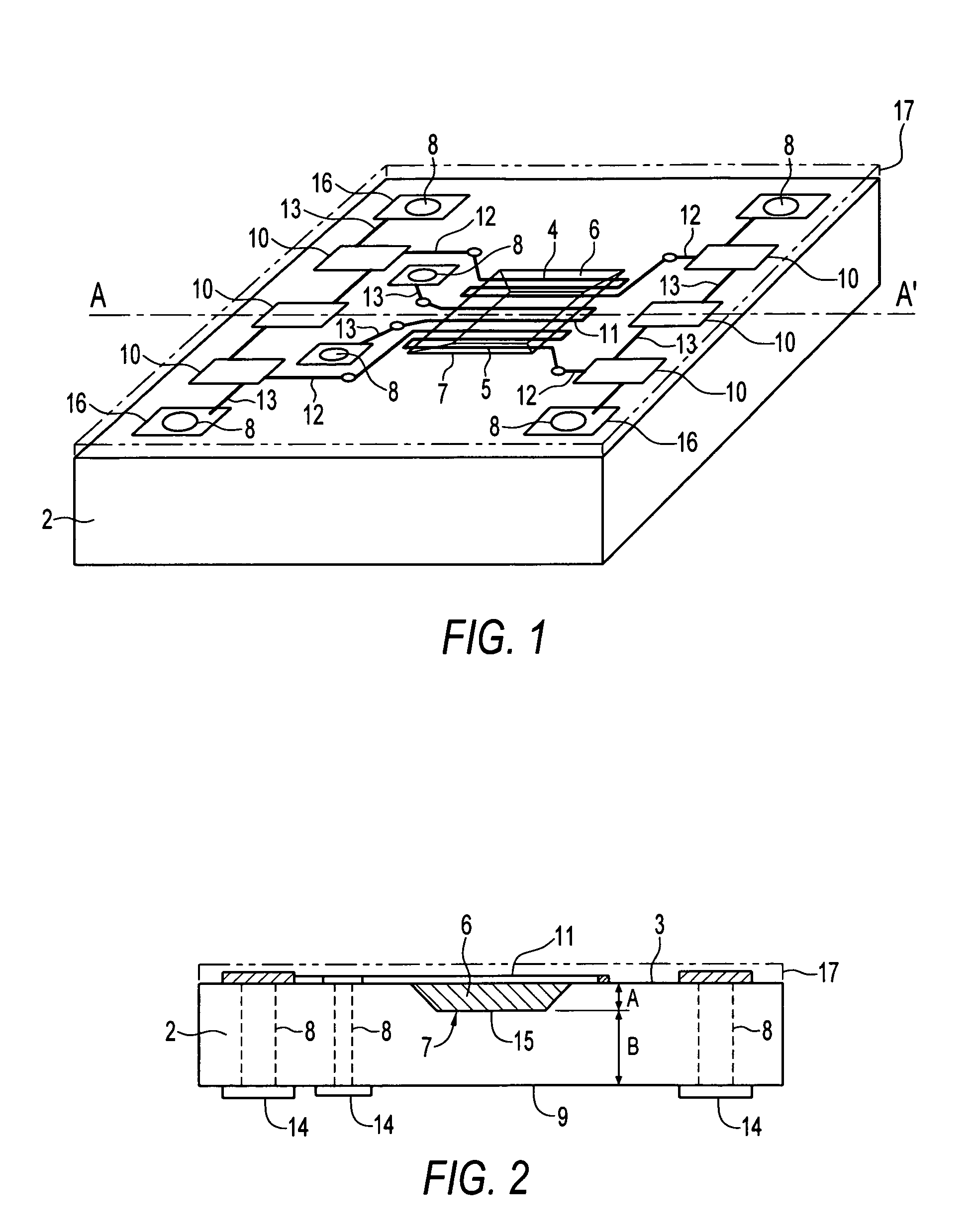
[0034]Referring the accompanying drawings, FIG. 1 illustrates a perspective view taken from above the fluid flow sensor according to one embodiment and FIG. 2 illustrates a partial cross-sectional view taken along line A-A′ of FIG. 1. The fluid flow sensor according to one embodiment generally consists of a thermal liquid flow sensor 1 comprising an integrated circuit substrate 2 having a surface 3 which, in the illustrative embodiment, is top surface 3, and a region of low thermal conductivity material 6 carried on the integrated circuit substrate at surface 3. The sensor 1 has at least one pair of temperature downstream / upstream sensing elements 4, 5 disposed on the low thermal conductivity region 6, an optional heating element 11, also dispo...


PUM


Abstract

A thermal fluid flow sensor and method of forming same. The flow sensor has an integrated circuit substrate, such as a silicon substrate, and a region of low thermal conductivity material carried on the top surface of the integrated circuit substrate. One or more pairs of temperature sensing elements are disposed on the low thermal conductivity region together with a heating element so that a robust flow sensor can be provided at low cost. Signal conditioning circuitry is disposed on the same surface as the temperature sensing elements and connected to the sensing elements thereby further reducing costs and improving the flow sensor sensitivity.

Description

TECHNICAL FIELD[0001]Embodiments are generally related to sensors, and in particular, to fluid flow sensors for sensing fluid properties, such as temperature, mass flow rate, temperature, thermal conductivity and specific heat. Embodiments are additionally related to thermal fluid flow sensors in the form of MEMS devices and methods of manufacturing such thermal fluid flow sensors. Embodiments are also related to low cost micro fluid flow sensor dies.BACKGROUND OF THE INVENTION[0002]Fluid flow sensors in the form of MEMS devices are configured to measure properties of fluid in contact with the sensors and provide output signals representative of the fluid flow rates. Thermal fluid flow sensors are configured to heat the fluid and measure the resulting thermal properties of the fluids to determine flow rates. Such thermal flow sensors generally include a microsensor die consisting of a substrate and one or more elements disposed on the substrate for heating the fluid and sensing the ...

Claims


Application Information

Patent Timeline
Patent Type & Authority Patents(United States)
IPC IPC(8): G01F1/68
CPCG01F1/6845G01F1/692
Inventor DAVIS, RICHARD A.PADMANABHAN, ARAVIND
Owner HONEYWELL INT INC
Why Eureka
Try Eureka