
Mass flowmeter

a mass flowmeter and coriolis technology, applied in the field of test and measurement instruments, can solve the problems of additional errors, inability to guarantee the absolute cleanliness the inability of two tubes to guarantee the complete cleaning of two tubes at the same time, so as to improve the performance of the resonant sensor and the mechanical quality factor, reduce the influence of the flow field drastically, and improve the effect of the mechanical quality factor

Inactive Publication Date: 2015-11-12
WALSN ENTERPRISES LTD
View PDF6 Cites 3 Cited by
  • Summary
  • Abstract
  • Description
  • Claims
  • Application Information

AI Technical Summary

Benefits of technology

This patent describes a new U-shaped CMF (Coriolis mass flow meter) that reduces the impact of flow field and has low flow resistance and pressure loss. It is easy to install and has good dynamic balance. The CMF can measure high viscosity liquids with high impurity content, and has increased performance and measurement range. The invention has a new U-shaped tube form with low flow resistance and pressure loss. It uses a duple distance-fixing mode and vacuum brazing for optimal installation position. The vibration exciter and detectors are used with the coil and magnet in cooperation to form a stable closed-loop system with low disturbance and self-adjustment capability.

Problems solved by technology

In practice, the distributer at the tube end cannot make sure the flow within the two tubes is absolutely equal; thus the deposit and the abrasion of the two tubes cannot guarantee being absolutely the same.
Therefore, the two tubes cannot guarantee being simultaneously cleaned completely when being cleaned.
As a result, the offset at zero point will occur during measurement, resulting in additional errors.
However, the curved tube type is likely to keep gas and fluid residues, which results in additional errors.
In addition, the curved tube type is more complex to be fabricated than the straight tube type.
It is not easy to be influenced by outside vibration due to its relatively high frequency which is far from the frequency of a general industrial mechanical vibration.
It is not easy to keep gas and the residues and has small profile size.
Therefore, it has low capability of preventing abrasion and corrosion.
The phase difference reflecting mass is in the level of microsecond, and thus the electric signal is more difficult to be processed, which severely limits the measurement range of the CMF.
In addition, the conventional vibrating straight tube typed CMF has low sensitivity, and is not immune to temperature fluctuation.
Its structure is usually a curved tube which has low stability of low speed, and the fluid is easy to be attached and deposited at the inner wall of the tube.
In addition, its fabrication and installation is complex, and it has poor characteristic of dynamic balance.
The comprehensive performance of the CMF measurement tube design is low, the tube installation is unstable, and the mechanics of the tube type is difficult to be implemented.
The measurement tube can be influenced by the design, fabrication and installation process, and it has poor characteristic of dynamic balance, which influences the performance of the CMF directly and irreversibly.

Method used


Image

  • Mass flowmeter
  • Mass flowmeter
  • Mass flowmeter

Examples


Embodiment Construction

[0036]Referring to the drawings, preferred embodiments of the present invention are further illustrated.

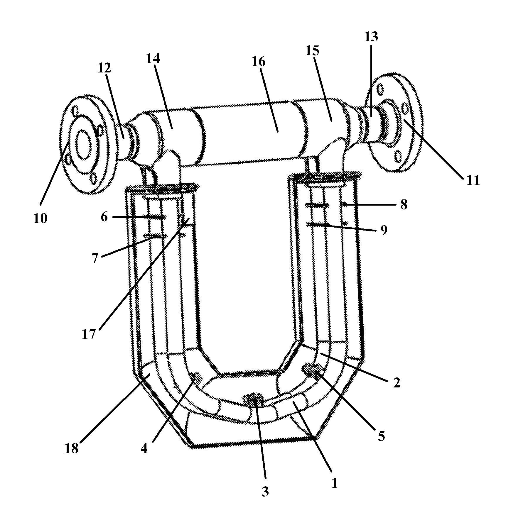
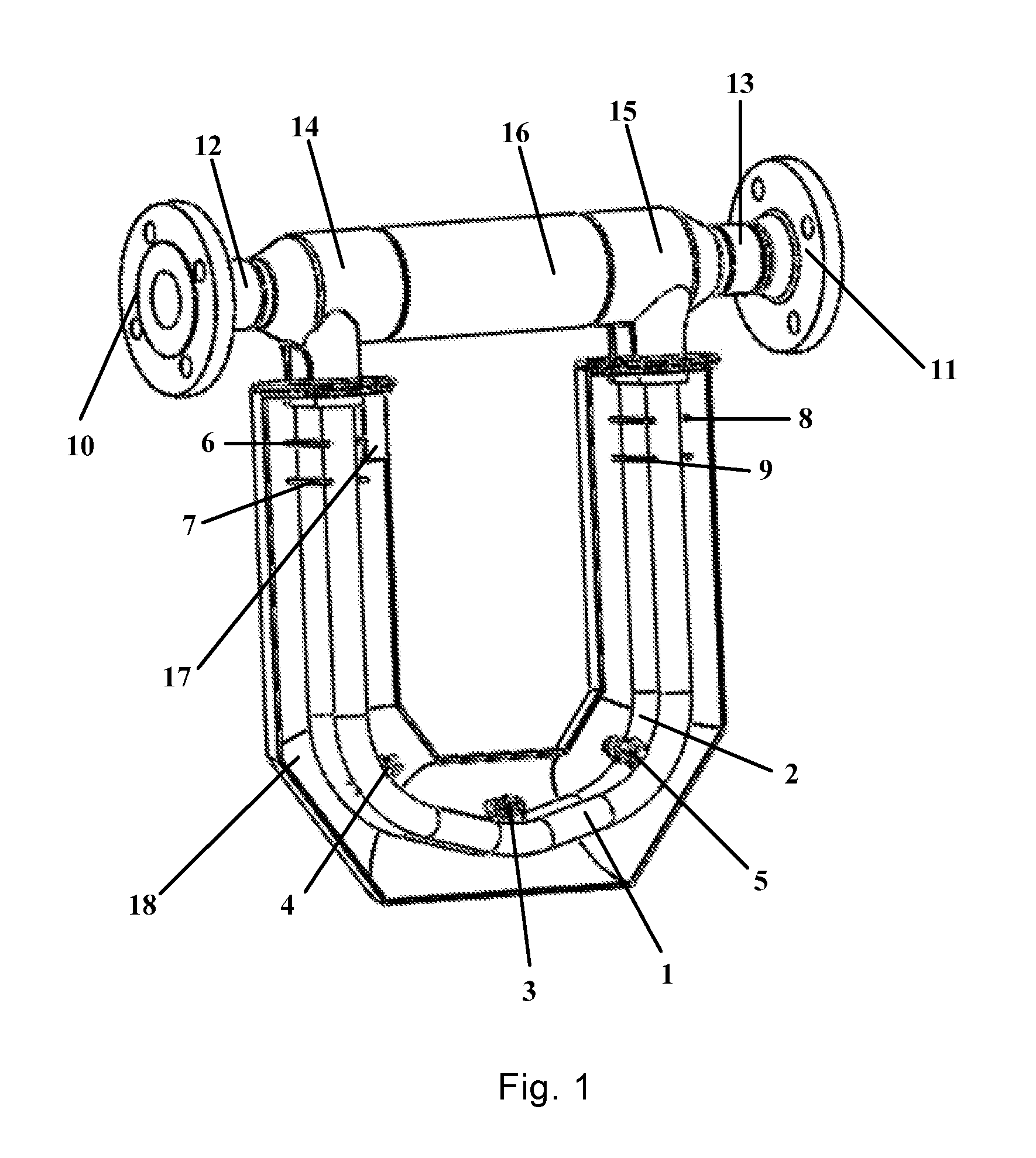
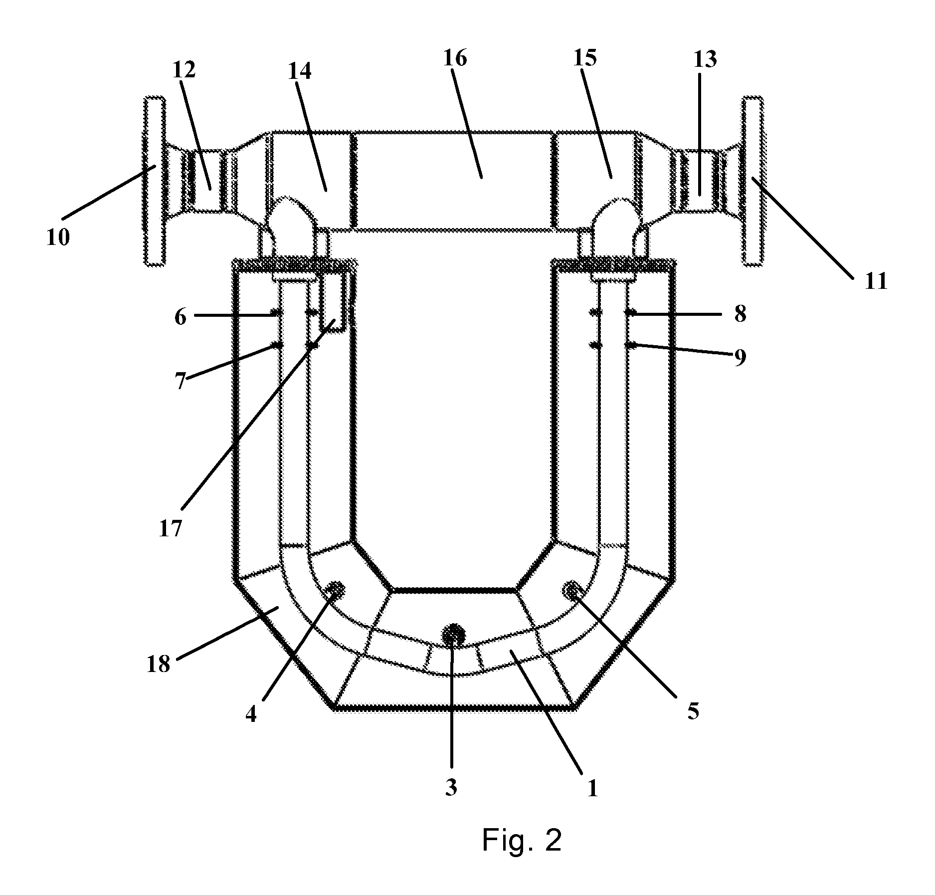
[0037]As shown in FIG. 1, a new U-shaped CMF of the present invention comprises two new U-shaped measurement tubes 1 and 2 with identical structures and sizes, a vibration exciter 3, two detectors 4 and 5, four distance plates 6, 7, 8 and 9, two flanges 10 and 11, two end connecting tubes 12 and 13, two flow dividers 14 and 15, one intermediate connecting tube 16, and a casing 18.

[0038]The two flanges 10 and 11 are respectively located at two outermost ends of the new U-shaped CMF. The two end connecting tubes 12 and 13 are respectively fabricated with the two flanges 10 and 11 in a manner of integral molding. Parts between the two end connecting tubes 12 and 13 and the two U-shaped measurement tubes 1 and 2 are referred to as the flow dividers 14 and 15. The two flow dividers 14 and 15 distribute a process medium to the two measurement tubes uniformly. The measurement tube with d...


PUM


Abstract

A mass flowmeter includes: a casing (18), two U-shaped measurement tubes (1, 2) with identical structures within the casing (18), a vibration exciter (3) installed at a center axis line of the two U-shaped measurement tubes (1, 2), two detectors (4, 5) respectively located at centers of second circular arc segments (22, 23), four distance plates (6, 7, 8, 9), two flanges (10, 11) respectively arranged at two outermost ends of the mass flowmeter symmetrically, two end connecting tubes (12, 13) connected to the U-shaped measurement tubes (1, 2) through two flow dividers (14, 15) which are connected to each other through an intermediate connecting tube (16), and a lead wire connector (17); wherein the two U-shaped measurement tubes (1, 2) are arranged in parallel, each of the U-shaped measurement tubes (1, 2) includes a first circular arc segment (19), wherein both sides of the first circular arc segment (19) are each connected to sloped tube segments (20, 21), the second circular arc segments (22, 23), and straight tube segments (24, 25) in sequence, and left half parts and right half parts of the U-shaped measurement tubes (1, 2) constitute a symmetrical structure relative to a center line of the first circular arc segment (19).

Description

CROSS REFERENCE OF RELATED APPLICATION[0001]This is a U.S. National Stage under 35 U.S.C. 371 of the International Application PCT / CN2013 / 090204, filed Dec. 23, 2013, which claims priority under 35 U.S.C. 119(a-d) to CN 201210585479.0, filed Dec. 31, 2012.BACKGROUND OF THE PRESENT INVENTION[0002]1. Field of Invention[0003]The present invention relates to a field of test and measurement instruments, and in particular to a new U-shaped Coriolis mass flowmeter.[0004]2. Description of Related Arts[0005]The mass flow measurement technology is an important development point of nations' technology in the process control field. In order to achieve high precision and high reliable measurement on various media under complex environments, Coriolis Mass Flowmeter (CMF) becomes one of the important developing technologies in the field and can meet great needs of the nations due to its superior performance CMF can directly measure the mass flow of the fluid within a pipe with high accuracy, and e...

Claims


Application Information

Patent Timeline
Patent Type & Authority Applications(United States)
IPC IPC(8): G01F1/84G01F15/14
CPCG01F1/8413G01F1/8422G01F1/8477G01F15/14G01F1/8409
Inventor SUN, XIAOJUN
Owner WALSN ENTERPRISES LTD
Learn More