
Differential MEMS device and methods

Active Publication Date: 2022-02-22
MOVELLA INC
View PDF10 Cites 1 Cited by
  • Summary
  • Abstract
  • Description
  • Claims
  • Application Information

AI Technical Summary

Benefits of technology

The present invention is about improving sensor performance using multiple MEMS devices. By using multiple sensors, the sensor can have better performance for parameters such as noise, temperature coefficient, and the like. The multiple MEMS devices can be in different orientations with each other and can provide redundant or differential data. This can make the sensor more suitable for applications requiring higher performance, such as for industrial applications. The MEMS devices can include accelerometers, gyroscopes, and magnetometers.

Problems solved by technology

Low cost sensor devices (e.g. MEMS) intended for consumer applications, tend to have modest performance for parameters such as noise, temp coefficient, etc.

Method used


Image

  • Differential MEMS device and methods
  • Differential MEMS device and methods
  • Differential MEMS device and methods

Examples


Embodiment Construction

[0019]In various embodiments of the present invention, three-axis accelerometers provided by the inventors of the present invention are characterized by having low noise for X and Y axis since theses axis are typically sensed using in-plane motion. Data from the X and Y axis tend to have less parasitic noise, etc. compared to data from Z axis since this axis is typically sensed using out of plane motion.

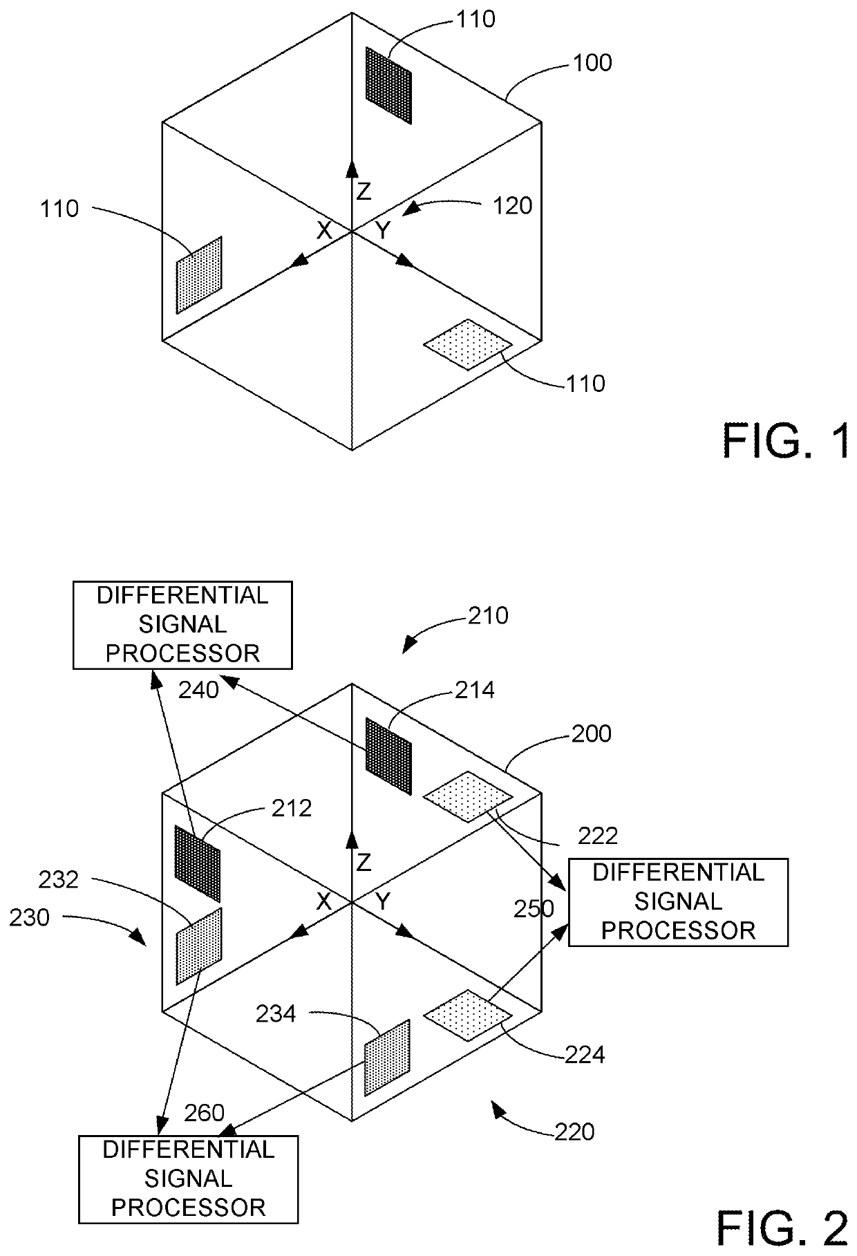
[0020]FIG. 1 illustrates various embodiments of the present invention. In this figure, a sensor 100 is illustrated having multiple MEMS devices 110 (e.g. accelerometers) that are mounted substantially orthogonally 120 with respect to each other. This type of mounting provides lower noise data for the acceleration on the z-axis. In some embodiments, two or more MEMS devices may be mounted on a substrate, e.g. three, four, five, six, or the like, and may be used to sense the perturbation. In various embodiments of the present invention, post processing at a sensor-hub can perform many ...


PUM


Abstract

A MEMS device includes a first MEMS sensor associated with a first spatial plane and a second MEMS sensor is associated with a spatial second plane not co-planar with the first spatial plane, wherein the first MEMS sensor is configured to provide a first interrupt and a first data in response to a physical perturbation, wherein the second MEMS sensor is configured to provide a second interrupt and second data in response to the physical perturbation, and a controller configured to receive the first interrupt at a first time and the second interrupt at a second time different from the first time, wherein the controller is configured to determine a latency between the first time and the second time, and wherein the controller is configured to determine motion data in response to the first data, to the second data, and to the latency.

Description

[0001]The present application claims benefit of U.S. Provisional Application No. 62 / 714,551 filed on Aug. 3, 2018, which is incorporated in its entirety herein.BACKGROUND OF THE INVENTION[0002]The present invention relates to sensors. More specifically, the present invention relates to improving sensor performance with the use of multiple MEMS devices.[0003]A constant challenge in the semiconductor space has been how to produce a high performance device for a low cost (low consumer price). An example of this is seen with microprocessors, where an Intel Core processor greatly outperforms an Intel Celeron processor, however is much more expensive. In the processor market, consumers often accept tradeoffs between processor performance and purchase price.[0004]A similar challenge also applies in the case of sensors, e.g. MEMS-based sensors including accelerometers, magnetometers, gyroscopes, pressure sensors e.g. microphones, and the like. More particularly, the challenge is how to prod...

Claims


Application Information

Patent Timeline
IPC IPC(8): G01P15/08G01P21/00B81B7/00G01P15/18
CPCG01P15/08B81B7/008G01P15/18G01P21/00B81B2201/0235B81B2201/0242B81B2201/0264G01P2015/0868B81B7/02B81B2201/0292
Inventor BHANDARI, SANJAYBELLUSCI, GIOVANNI
Owner MOVELLA INC
Learn More