Touch panel control circuit

a control circuit and touch panel technology, applied in the direction of instruments, computing, electric digital data processing, etc., can solve the problems of not actively supporting multi-touch operations, unable to distinguish between output voltage and output voltage of the panel, and no technique has been disclosed, so as to reduce the combined resistance of the path from the first terminal up to the second terminal, increase the panel current, and reduce the combined resistance

Active Publication Date: 2014-06-19
ROHM CO LTD
View PDF6 Cites 4 Cited by
  • Summary
  • Abstract
  • Description
  • Claims
  • Application Information

AI Technical Summary

Benefits of technology

[0021]When the user is touching the two points, the path between the two points is configured as the first resistive film and the second resistive film connected in parallel. Accordingly, the combined resistance of a path from the first terminal up to the second terminal is reduced, thereby increasing the panel current. As the distance between the two points is greater, the distance of the path thus configured as the first resistive film and the second resistive film connected in parallel becomes greater. This reduces the combined resistance, thereby increasing the panel current. Thus, such an arrangement is capable of determining the interval between the coordinates of the two points based on the panel current.

Problems solved by technology

However, such touch panels have been realized only as electrostatic sensor touch panels, and have not been realized as resistive film touch panels.
However, such an arrangement is not capable of distinguishing between the output voltage of the panel in a case in which the user touches two positions (multi-touch operation) and the output voltage thereof in a case in which the user touches a single position (single touch operation).
However, this touch panel input apparatus handles such multi-touch operations as an input error.
That is to say, such an arrangement does not actively support multi-touch operations as valid input operations.
Thus, no technique has been disclosed which identifies the multiple coordinates involved in such a multi-touch operation.

Method used


Image

  • Touch panel control circuit
  • Touch panel control circuit
  • Touch panel control circuit

Examples


Embodiment Construction

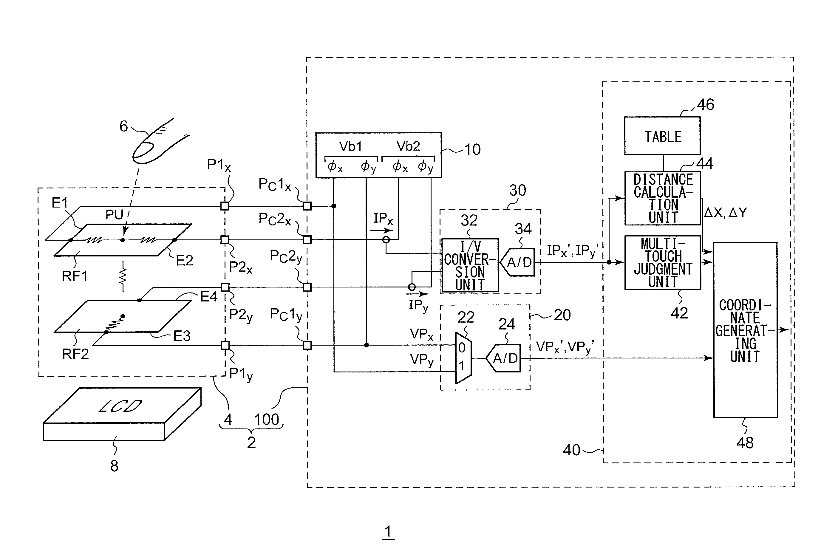
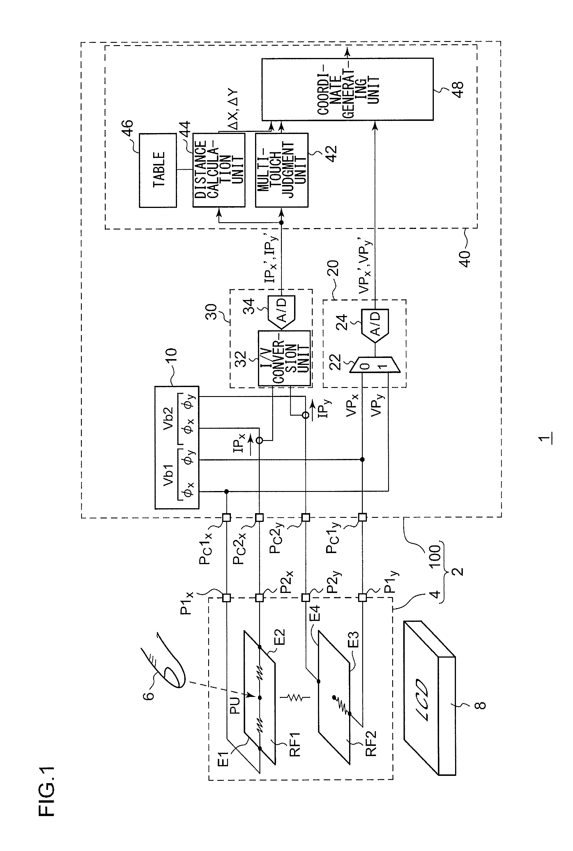
[0038]The invention will now be described based on preferred embodiments which do not intend to limit the scope of the present invention but exemplify the invention. All of the features and the combinations thereof described in the embodiment are not necessarily essential to the invention.

[0039]In the present specification, the state represented by the phrase “the member A is connected to the member B” includes a state in which the member A is indirectly connected to the member B via another member that does not substantially affect the electric connection therebetween, or that does not damage the functions or effects of the connection therebetween, in addition to a state in which the member A is physically and directly connected to the member B.

[0040]Similarly, the state represented by the phrase “the member C is provided between the member A and the member B” includes a state in which the member A is indirectly connected to the member C, or the member B is indirectly connected to ...


PUM


Abstract

A voltage generating unit includes an output transistor arranged as a first-terminal side extension of a path that includes a first terminal, a first resistive film, and a second terminal, and is configured to apply a first bias voltage to the first terminal. A current detection unit includes a detection transistor connected to the output transistor such that they form a current mirror circuit, a detection resistor arranged on a path of the detection transistor, and an amplifier circuit configured to amplify the difference between a voltage drop across a detection resistor and a predetermined voltage, and to output the difference thus amplified as a value which represents a panel current.

Description

BACKGROUND OF THE INVENTION[0001]1. Field of the Invention[0002]The present invention relates to a resistive film touch panel, and particularly to a technique for detecting a simultaneous touch state (multi-touch state) in which the user touches multiple points.[0003]2. Description of the Related Art[0004]In recent years, it has become mainstream for electronic devices such as computers, cellular phone terminals, PDAs (Personal Digital Assistants), etc., to include an input apparatus which allows the user to operate the electronic device by using the fingers to touch the input apparatus. Known examples of such input apparatuses include resistive film touch panels (touch sensors). A related technique is disclosed in Japanese Patent Application Laid Open No. 2009-48233.[0005]In recent years, there is a demand for a touch panel which supports multi-touch operations. However, such touch panels have been realized only as electrostatic sensor touch panels, and have not been realized as re...

Claims


Application Information

Patent Timeline
Patent Type & Authority Applications(United States)
IPC IPC(8): G06F3/041
CPCG06F3/0416G06F3/04186G06F3/045G06F2203/04104
Inventor ABE, SHINICHI
Owner ROHM CO LTD
Why Eureka
Try Eureka