Pulse-Width Modulated Signal Generator for Light-Emitting Diode Dimming

Inactive Publication Date: 2011-03-31
SYNAPTICS INC
View PDF7 Cites 40 Cited by
  • Summary
  • Abstract
  • Description
  • Claims
  • Application Information

AI Technical Summary

Benefits of technology

[0007]A circuit to control light-emitting-diode (LED) dimming of a display panel is provided. The circuit includes a first stage to receive a first PWM signal from an application driver, the first PWM signal having a first frequency and a first duty cycle.

Problems solved by technology

This approach places an inconvenient restriction on the marketability of the LCD panel, or unduly increases its design cost.

Method used


Image

  • Pulse-Width Modulated Signal Generator for Light-Emitting Diode Dimming
  • Pulse-Width Modulated Signal Generator for Light-Emitting Diode Dimming
  • Pulse-Width Modulated Signal Generator for Light-Emitting Diode Dimming

Examples


Embodiment Construction

[0020]The figures and the following description relate to some embodiments of the present invention by way of illustration only. It should be noted that from the following discussion, alternative embodiments of the structures and methods disclosed herein will be readily recognized as viable alternatives that may be employed without departing from the principles of the present invention.

[0021]Reference will now be made in detail to several embodiments of the present invention(s), examples of which are illustrated in the accompanying figures. It is noted that, wherever practicable, similar or like reference numbers may be used in the figures and may indicate similar or like functionality. The figures depict embodiments of the present invention for purposes of illustration only. One skilled in the art will readily recognize from the following description that alternative embodiments of the structures and methods illustrated herein may be employed without departing from the principles o...


PUM


Abstract

A circuit to control light-emitting-diode (LED) dimming of a display panel, is provided. The circuit includes a first stage to receive an incoming PWM signal from an application driver, the incoming PWM signal having a first frequency and a first duty cycle. A second stage in the circuit is provided to produce and transmit an output PWM signal, the second PWM signal having a second frequency according to the characteristics of the display panel, a second duty cycle.

Description

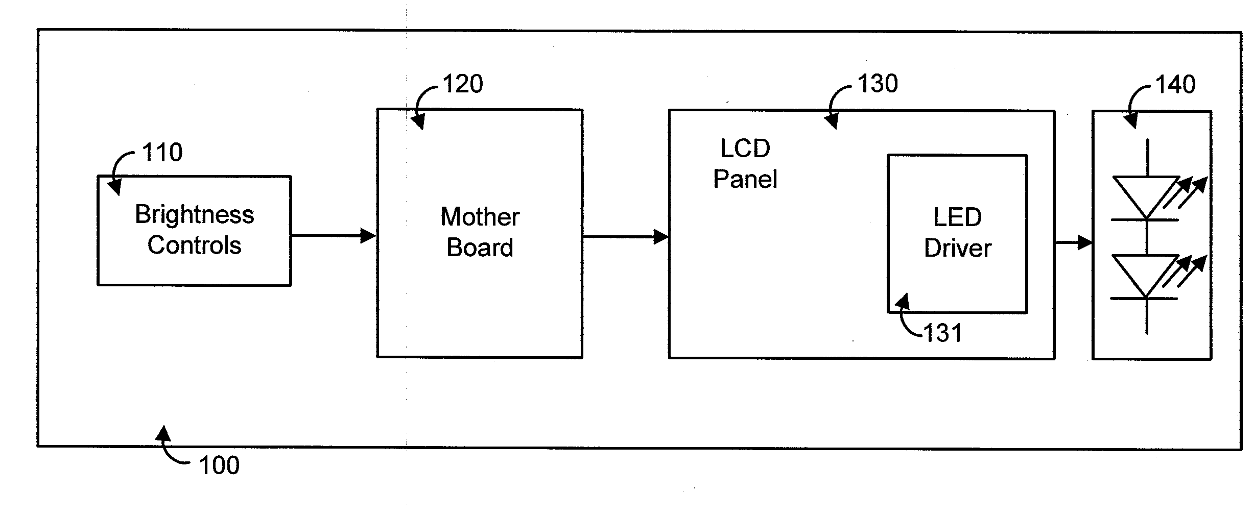
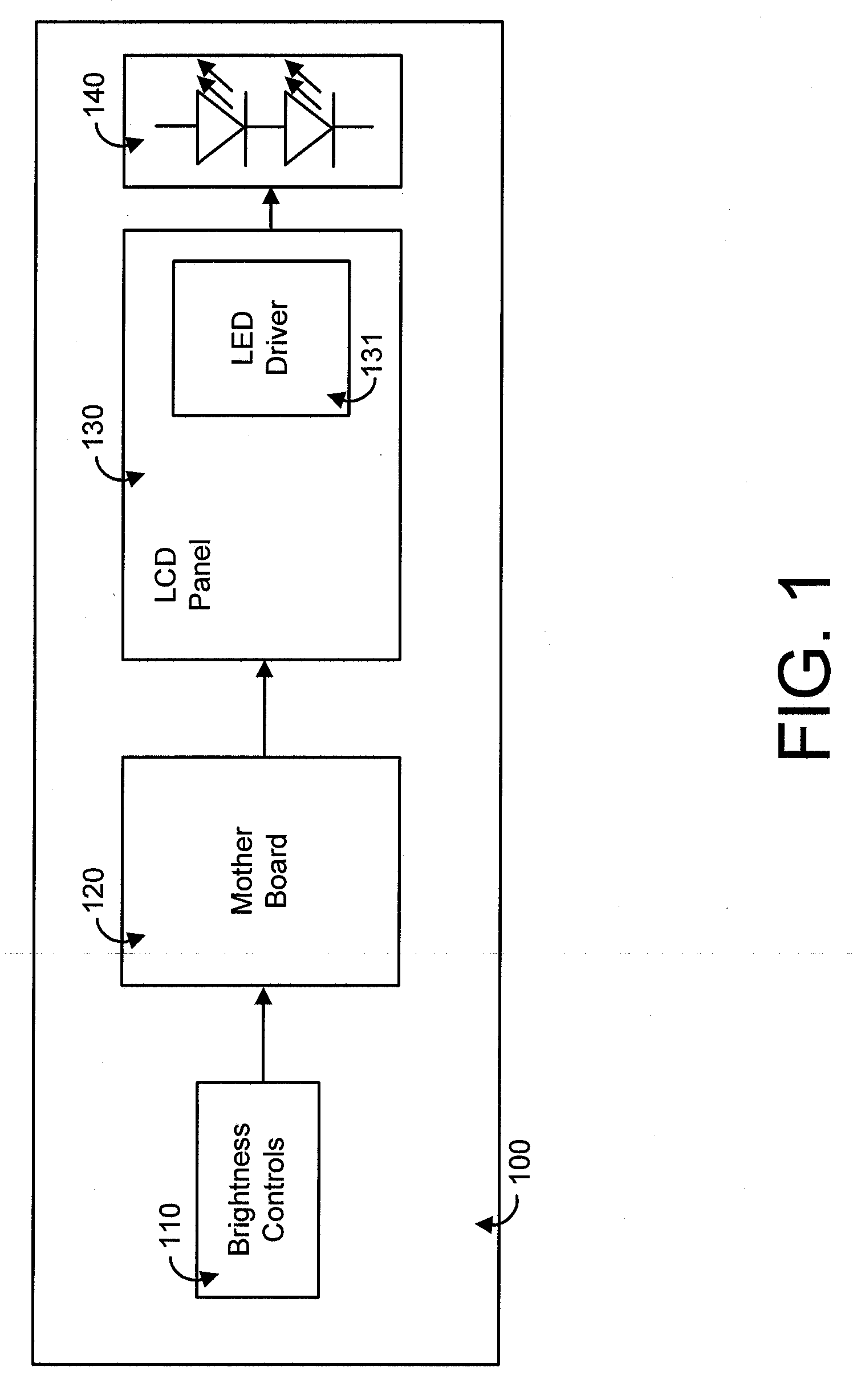
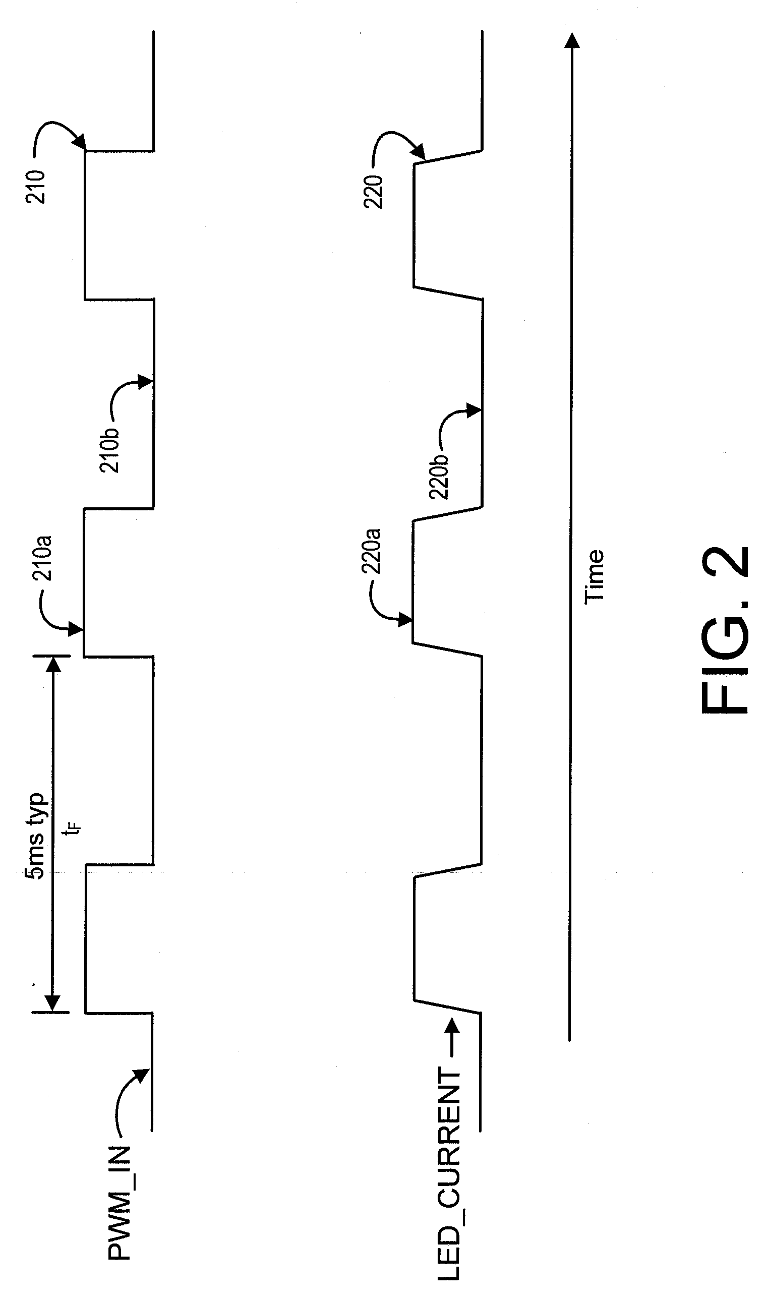
BACKGROUND[0001]1. Field of the Invention[0002]Embodiments of the present invention relate to light-emitting diode dimming and, in particular, to a pulse-width modulated signal generator for light-emitting diode dimming.[0003]2. Description of Related Art[0004]In current display systems LED dimming is accomplished by using a PWM input as a brightness control. This input signal acts as an ON / OFF control for backlight LEDs. As the duty cycle of the PWM signal changes, so does the time during which LEDs are ON, resulting in adjustable brightness. The brightness of the display is thus independent of the frequency of operation of the LED driving circuit, and is only a function of the duty cycle of the PWM driving signal. The frequency of the PWM signal is usually selected above 100 Hz in order to provide flicker-free operation. However, LCD panel manufacturers often desire operation frequencies much higher than 100 Hz (typically, about 2 kHz) in order to more drastically reduce flicker.[...

Claims


Application Information

Patent Timeline
IPC IPC(8): H05B37/02
CPCH05B33/0818Y02B20/346H05B33/0827H05B45/325H05B45/46Y02B20/30
Inventor GODER, DIMITRY
Owner SYNAPTICS INC
Why Eureka
Try Eureka