

Control of motor velocity of a surgical stapling and cutting instrument based on angle of articulation
a technology of motor velocity and surgical stapling, applied in the field of surgical stapling and cutting instruments, and the field of surgical staple cartridges, can solve the problems of end effectors articulating or further articulating undesired
Active Publication Date: 2018-12-20
CILAG GMBH INT
View PDF7 Cites 128 Cited by
- Summary
- Abstract
- Description
- Claims
- Application Information
AI Technical Summary
Benefits of technology
The patent describes a surgical instrument that has an articulation joint and a motor to move the instrument. The instrument can be in a hold position to prevent articulation. The instrument also has a control circuit that detects the position of the articulation joint and a predetermined threshold to control the movement of the instrument. The control circuit can engage or disengage the motor to move the instrument. The instrument can also have a longitudinal shaft assembly with a rotatable shaft and a drive gear to move the instrument. The control circuit can control the movement of the instrument by engaging or disengaging the motor. The instrument can also have a power source and a dynamic brake condition to control the movement of the instrument. The technical effects of the patent are improved precision and control of the surgical instrument during surgical procedures.
Problems solved by technology
During use of a motorized surgical stapling and cutting instrument it is possible that the end effector may articulate or further articulate undesirably due to externally applied loads.
Method used
View moreImage
Smart ImageViewing Examples

Examples
example 2
[0197]The surgical instrument of Example 1, wherein the control circuit is configured to maintain the articulation position in response to the movement of the articulation member that exceeds the predetermined threshold.
example 3
[0198]The surgical instrument of Example 2, wherein the control circuit is configured to apply pulse width modulated (PWM) current to the motor in the hold condition to resist the movement of the articulation member.
example 4
[0199]The surgical instrument of Example 1 through Example 3, wherein the motor comprises a DC brushed motor.
Login to View More PUM
 Abstract
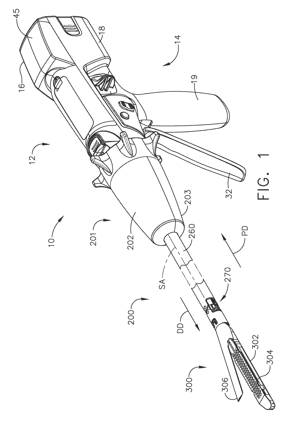
A motorized surgical instrument is disclosed. The surgical instrument includes a control circuit configured to control the movement of an end effector. If the end effector moves outside a predetermined acceptable range, the control circuit may create a dynamic brake to resist the undesired movement of the end effector. The control circuit may apply pulse width modulated (PWM) current to resist the undesired movement of the end effector outside a predetermined acceptable range.
Description
TECHNICAL FIELD[0001]The present disclosure relates to surgical instruments and, in various circumstances, to surgical stapling and cutting instruments and staple cartridges therefor that are designed to staple and cut tissue.BACKGROUND[0002]In a motorized surgical stapling and cutting instrument it may be useful to control the velocity of a cutting member or to control the articulation velocity of an end effector. Velocity of a displacement member may be determined by measuring elapsed time at predetermined position intervals of the displacement member or measuring the position of the displacement member at predetermined time intervals. The control may be open loop or closed loop. Such measurements may be useful to evaluate tissue conditions such as tissue thickness and adjust the velocity of the cutting member during a firing stroke to account for the tissue conditions. Tissue thickness may be determined by comparing expected velocity of the cutting member to the actual velocity o...
Claims
Login to View More Application Information
Patent Timeline
 IPC IPC(8): A61B17/16A61B34/00
CPCA61B17/1626A61B34/76A61B2017/320052A61B2017/00022A61B2017/00039H02K7/116H02P6/24A61B17/07207A61B17/3209A61B2017/07271A61B2017/07285A61B2017/00017A61B2017/00115A61B2017/00398A61B2017/0046A61B2017/00734A61B2017/2927A61B2090/067
InventorSHELTON, IV, FREDERICK E.YATES, DAVID C.HARRIS, JASON L.
OwnerCILAG GMBH INT