Systems and methods for load detection and correction in a digital amplifier

a digital amplifier and load detection technology, applied in the field of audio amplification systems, can solve the problems of low performance applications, complex and costly applications to implement, and the solution is not widely accepted, and achieves the effect of less complex, easy implementation and maintenan

Active Publication Date: 2007-03-15
INTERSIL INC
View PDF10 Cites 117 Cited by
  • Summary
  • Abstract
  • Description
  • Claims
  • Application Information

AI Technical Summary

Benefits of technology

[0018] The various embodiments of the present invention may provide a number of advantages over the prior art. For example, the embodiments of the present invention may be much less complex and easier to implement and maintain than in comparable prior art systems. Prior art systems that attempt to perform load detection typically measure output current and voltage with RMS-to-DC converters, then perform an A/D conversion on the full measured values, and then calculate the result of the voltage divided by the current. The present embodiments instead perform a simple comparison of analog values and produce a binary over-thres...

Problems solved by technology

More particularly, these attempts utilized analog modulation schemes that resulted in low performance applications.
These applications were complex and costly to implement.
Consequently, these solutions were not widely accepted.
Prior art analog implementations of Class D technology have therefore been unable to displace legacy Class AB amplifiers in mainstream amplifier applications.
These digital PWM schemes, however, did little to offset the major barriers to integration of PWM modulators into the total amplifier solution.
Class D technology has therefore continued to be unable to displace legacy Class AB amplifiers in mainstream applications.
One o...

Method used


Image

  • Systems and methods for load detection and correction in a digital amplifier
  • Systems and methods for load detection and correction in a digital amplifier
  • Systems and methods for load detection and correction in a digital amplifier

Examples


Embodiment Construction

[0027] One or more embodiments of the invention are described below. It should be noted that these and any other embodiments described below are exemplary and are intended to be illustrative of the invention rather than limiting.

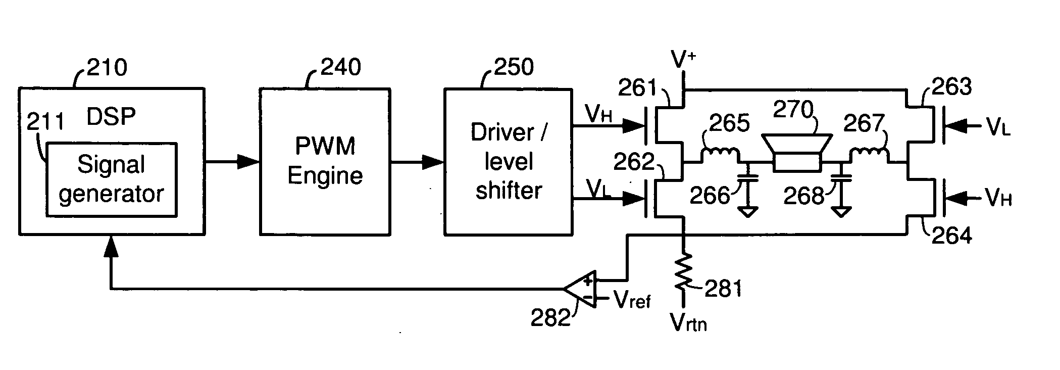
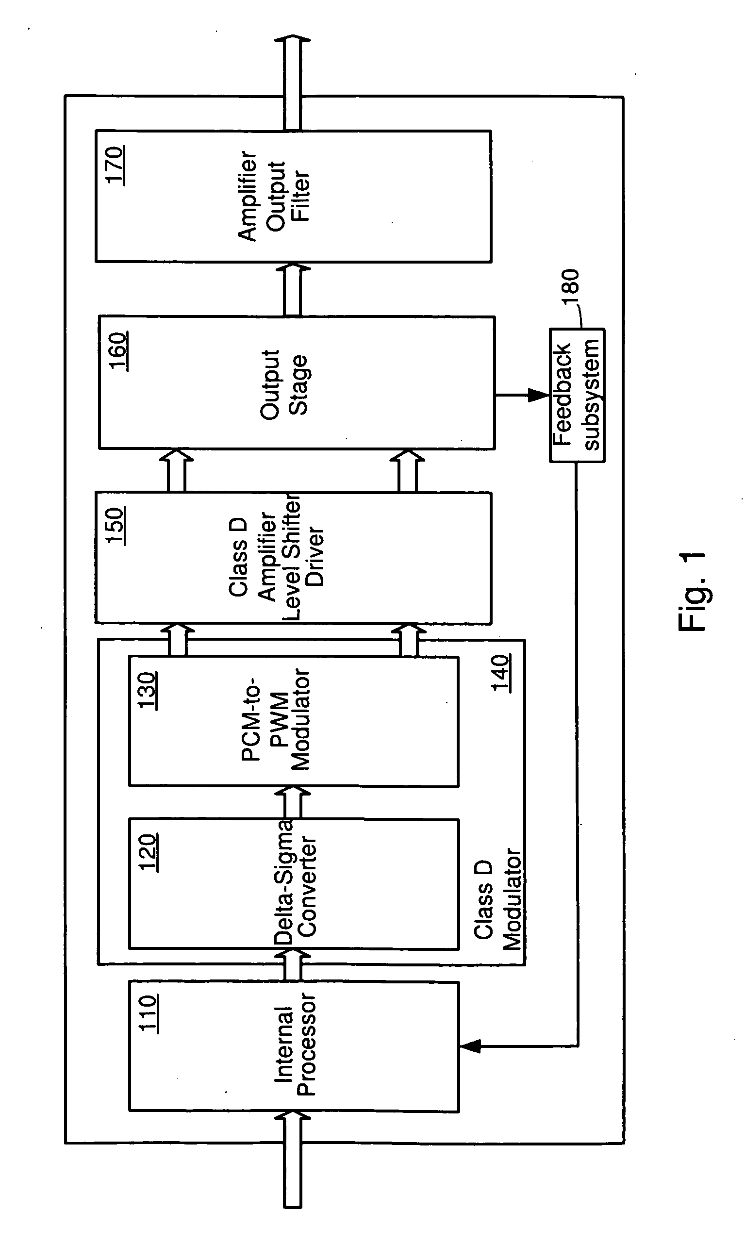
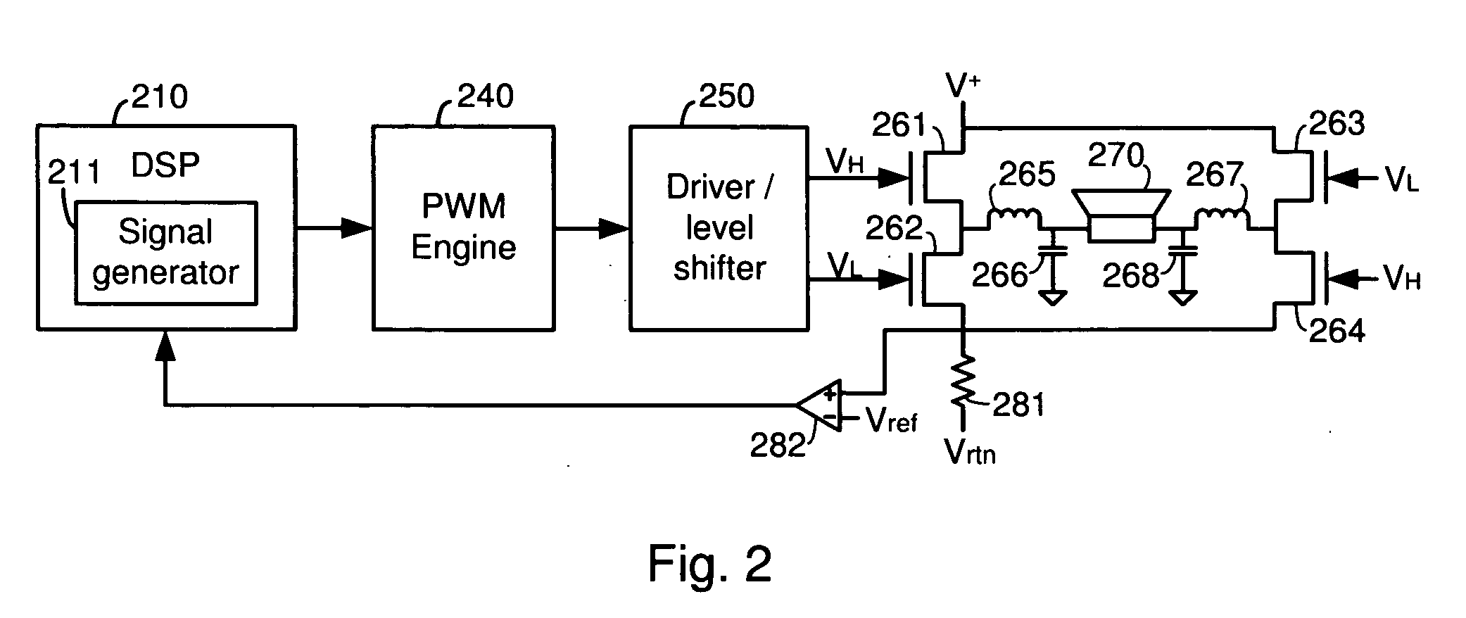
[0028] As described herein, various embodiments of the invention comprise systems and methods for detecting the impedance of an output load coupled to a digital amplifier and compensating for changes in the frequency response of the amplifier. One embodiment is implemented in a Class D pulse width modulated (PWM) amplifier. A mechanism is provided for determining the impedance of a speaker that is coupled to the output of the amplifier. The processing of the digital audio signal is then adjusted if necessary to optimize the frequency response of the amplifier for the specific impedance of the speaker.

[0029] In this embodiment, a digital test signal (e.g., a sine wave) is generated. This test signal is processed by the amplifier to produce a corresponding a...


PUM


Abstract

Systems and methods for detecting the impedance of an output load coupled to a digital amplifier and compensating for changes in the response of the amplifier. One embodiment of the invention is implemented in a Class D pulse width modulated (PWM) amplifier. In this embodiment, a digital PCM test signal is generated. This test signal is processed by the amplifier to produce a corresponding analog audio output signal that is used to drive a speaker. A sense resistor placed in series with the speaker is used to generate a test voltage that is compared to a reference voltage. When the test voltage reaches the reference voltage, the current through the sense resistor (hence the speaker) is at a known level, so the value of the digital test signal is noted. The impedance of the speaker is then determined from the test signal value and the speaker current.

Description

RELATED APPLICATIONS [0001] This application claims priority to U.S. patent application Ser. No. 10 / 805,741, entitled “Systems And Methods For Automatically Adjusting Channel Timing,” by Taylor, et al., filed Mar. 22, 2004, which claims priority to: U.S. Provisional Patent Application No. 60 / 456,421, entitled “Output Device Switch Timing Correction,” by Taylor, et al., filed Mar. 21, 2003; U.S. Provisional Patent Application No. 60 / 456,414, entitled “Adaptive Anti-Clipping Protection,” by Taylor, et al., filed Mar. 21, 2003; U.S. Provisional Patent Application No. 60 / 456,430, entitled “Frequency Response Correction,” by Taylor, et al., filed Mar. 21, 2003; U.S. Provisional Patent Application No. 60 / 456,429, entitled “High-Efficiency, High-Performance Sample Rate Converter,” by Andersen, et al., filed Mar. 21, 2003; U.S. Provisional Patent Application No. 60 / 456,422, entitled “Output Filter, Phase / Timing Correction,” by Taylor, et al., filed Mar. 21, 2003; U.S. Provisional Patent App...

Claims


Application Information

Patent Timeline
IPC IPC(8): H03F3/38
CPCH03F1/523H03F3/2173H03F2200/426H03F2200/331H03F3/2175
Inventor HAND, LARRY E.TAYLOR, WILSON E.
Owner INTERSIL INC
Why Eureka
Try Eureka