Method for localizing an optical network termination in an optical access network
Active Publication Date: 2011-03-31
TELECOM ITALIA SPA
View PDF2 Cites 8 Cited by
Summary
Abstract
Description
Claims
Application Information
AI Technical Summary
This helps you quickly interpret patents by identifying the three key elements:
Problems solved by technology
Method used
Benefits of technology
Benefits of technology
[0011]Indeed, when a user buys or leases an ONT, for accessing broadband services from his apartment he simply has to connect the ONT to the plug. This operation is very simple and short, thanks to the passive nature of the PON. However, the passive nature of the PON disadvantageously does not allow to check whether the user is accessing the broadband services from his apartment or from another apartment served by the same ODN.
[0019]Accordingly, the Applicant has tackled the problem of providing a method for localizing an optical network termination of an optical access network (in particular, but not exclusively, a PON) which allows the service provider to check that the optical network termination is always used by connecting it to the optical link which has been declared by the user upon subscription, even when in the optical access network different optical links have substantially the same length.
Problems solved by technology
The Applicant has noticed that, disadvantageously, in case of FTTH applications, when a user connects his ONT to a plug of a PON, the OLT is not able to localize the ONT, i.e. to identify the plug (i.e. the optical link) to which the ONT has been connected.
However, the passive nature of the PON disadvantageously does not allow to check whether the user is accessing the broadband services from his apartment or from another apartment served by the same ODN.
Image
Click on the blue label to locate the original text in one second.
Reading with bidirectional positioning of images and text.
Examples
first embodiment
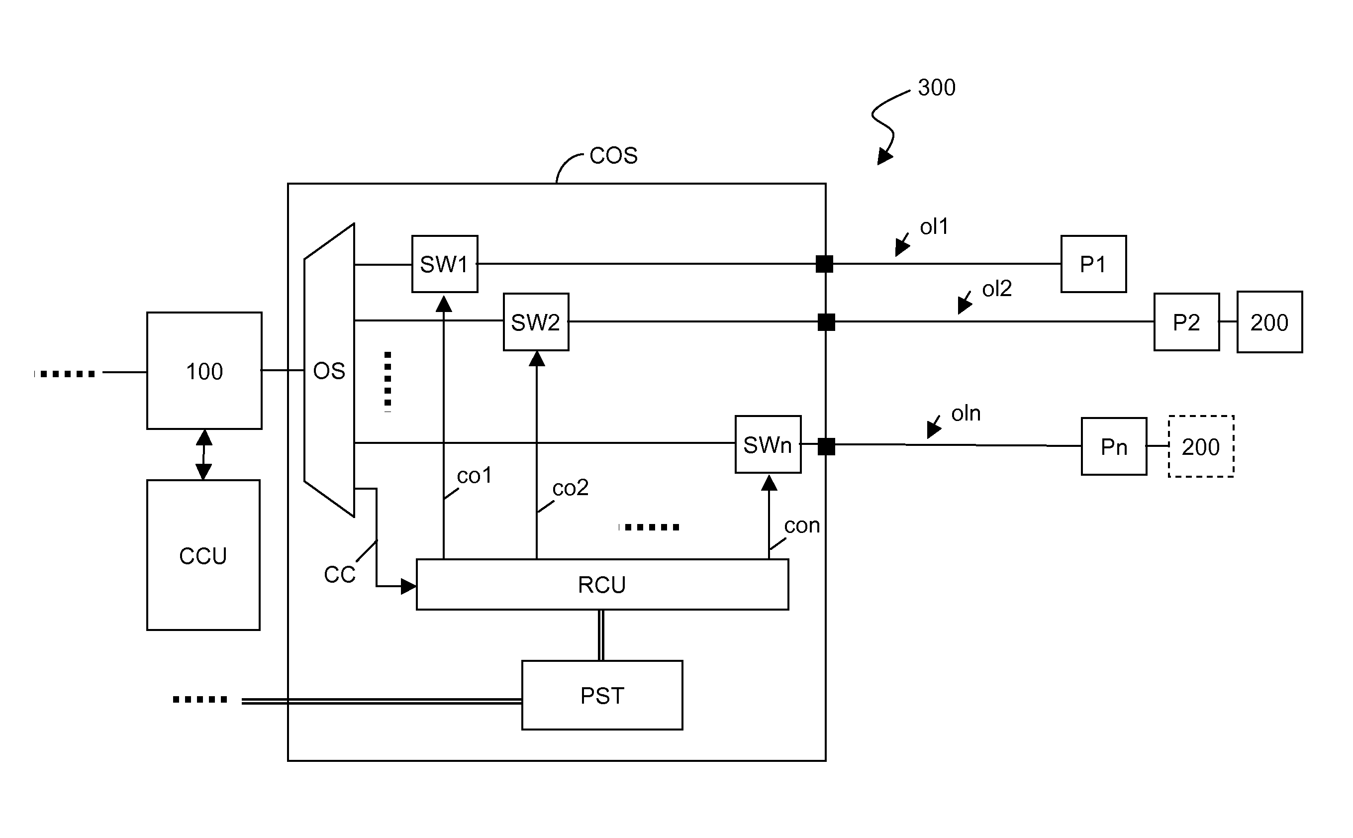
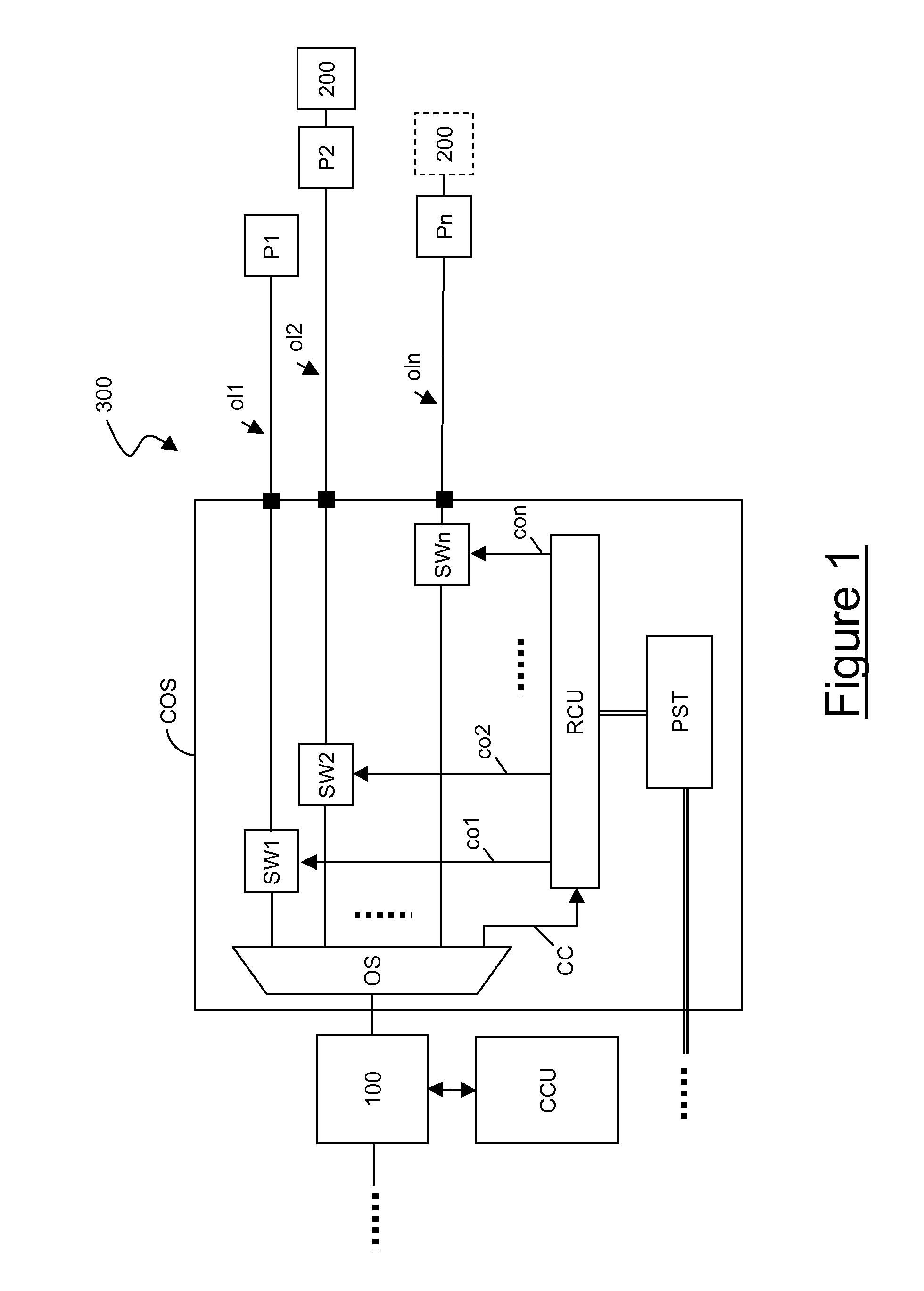
[0043]FIG. 1 schematically shows a PON suitable for implementing the method according to the present invention.
[0044]The PON of FIG. 1 preferably comprises an OLT 100, a central control unit CCU cooperating with the OLT 100 and an ODN 300. Preferably, the ODN comprises a number n of optical links ol1, ol2, . . . , oln, a number n of plugs P1, P2, . . . , Pn, and a controllable optical splitter COS. The ODN may also comprise optical splitters, other controlled optical splitters and other optical links connected to the OLT 100, which for simplicity are not shown in FIG. 1.
[0045]Preferably, each optical link ol1, ol2, . . . , oln comprises an optical fiber. More preferably, the optical fiber is a silica-based single-mode standard optical fiber of the type mentioned above. Preferably, the number n of optical links is equal to 7, 15, 31, 63 or 127. The optical links ol1, ol2, . . . , oln may have all a same length, or they may have different lengths.
[0046]The OLT 100 and the central cont...
second embodiment
[0076]FIG. 3 schematically shows a PON suitable for implementing the method according to the present invention.
[0077]The comparison of FIG. 1 and FIG. 3 shows that the only difference between the two PONs is that the optical switches SW1, SW2, . . . , SWn of FIG. 1 are replaced by variable optical attenuators VA1, VA2, . . . , VAn. As known in the art, a variable optical attenuator is an optical element inducing an optical attenuation on an optical signal passing through it, the optical attenuation being controllable e.g. by means of mechanical means (e.g. a screw to be turned for adjusting the optical attenuation) or electronic means (e.g. a processor controlling the optical variable attenuator and having an interface by means of which a desired optical attenuation may be set).
[0078]According to first variants of this second embodiment, the optical splitter OS and the variable optical attenuators VA1, VA2, . . . , VAn are discrete components.
[0079]According to second variants, the ...
PUM
Abstract
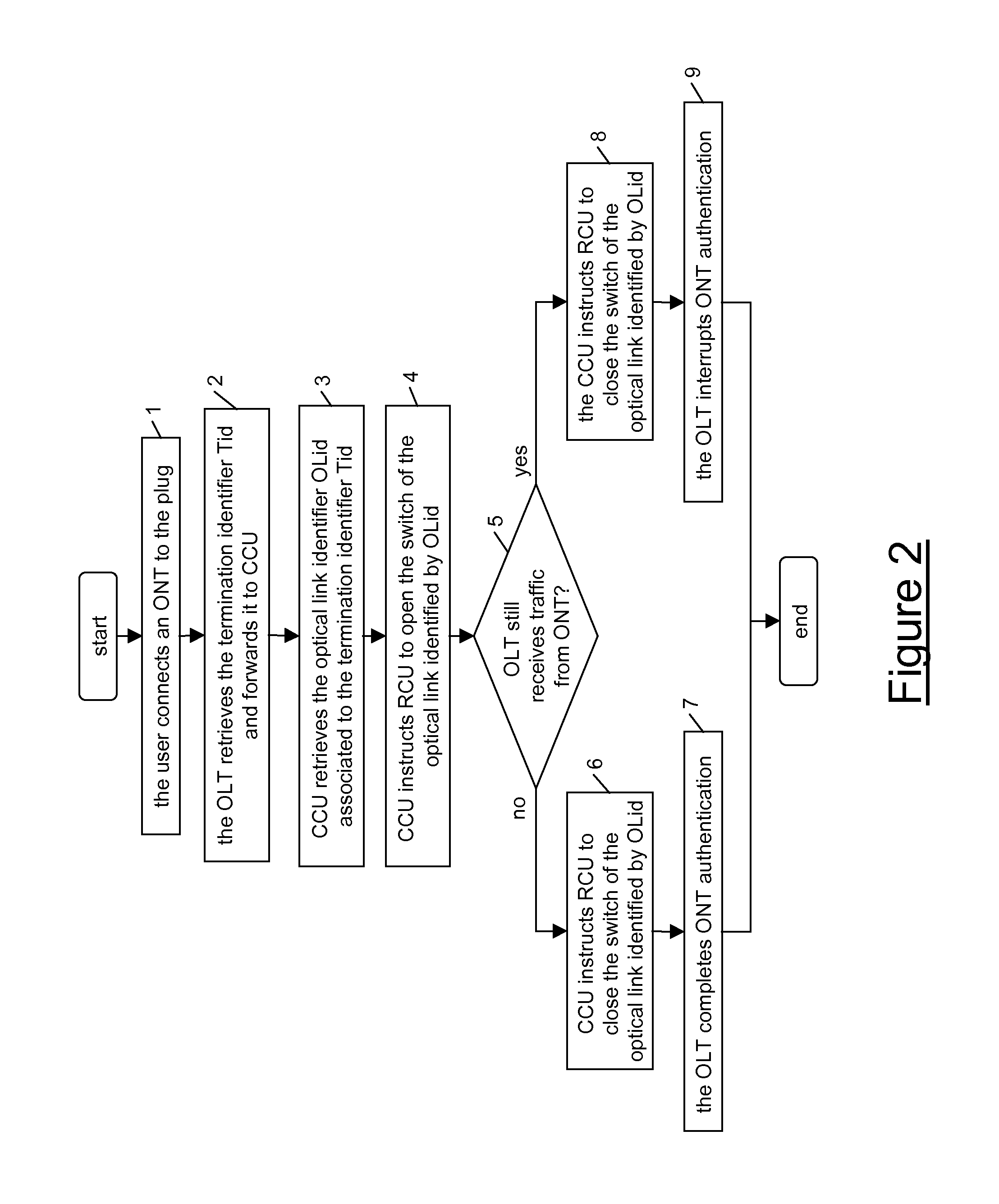
A method for localizing an optical network termination in an optical access network including an optical line termination and a number of optical links. The method includes: detecting that the optical network termination is connected to an optical link and retrieving from it a termination identifier univocally identifying the optical network termination, using the termination identifier for retrieving an optical link identifier associated with the termination identifier and univocally identifying a given optical link of the optical links; inducing a change in an optical connection between the optical line termination and the given optical link, thus modifying an optical parameter of first optical signals received at the optical line termination through the given optical link; checking whether second optical signals received at the optical line termination from the optical network termination are affected by the change; and in the affirmative, determining that the optical network termination is connected to the first optical link.
Description
TECHNICAL FIELD[0001]The present invention generally relates to the field of optical access networks. In particular, the present invention relates to a method for localizing an optical network termination in an optical access network. Further, the present invention relates to an optical access network suitable for implementing the above method.BACKGROUND ART[0002]It is known that an optical access network allows a plurality of users to access a number of broadband services, such as for instance Internet access, video-on-demand and telephone services.[0003]Among the known optical access networks, passive optical networks (briefly termed PON) are becoming even more widespread. Typically, a PON comprises an optical line termination (briefly termed OLT) and an optical distribution network (briefly termed ODN). The ODN comprises a plurality of optical links (typically comprising silica-based single-mode standard optical fibers) and optical splitters arranged so as to form a tree structur...
Claims
Application Information
Patent Timeline
Application Date:The date an application was filed.
Publication Date:The date a patent or application was officially published.
First Publication Date:The earliest publication date of a patent with the same application number.
Issue Date:Publication date of the patent grant document.
PCT Entry Date:The Entry date of PCT National Phase.
Estimated Expiry Date:The statutory expiry date of a patent right according to the Patent Law, and it is the longest term of protection that the patent right can achieve without the termination of the patent right due to other reasons(Term extension factor has been taken into account ).
Invalid Date:Actual expiry date is based on effective date or publication date of legal transaction data of invalid patent.
