Piezoelectric micro-blower

a micro-blower and micro-piezoelectric technology, applied in the direction of positive displacement engines, flexible wall reciprocating engines, piston pumps, etc., can solve the problems of direct leakage of vibration of ultrasonic drivers to the outside, increase energy loss, increase energy loss, etc., to achieve easy vibration, increase the displacement of the top plate of the inner case, increase the effect of vibrating

Active Publication Date: 2011-03-31
MURATA MFG CO LTD
View PDF10 Cites 90 Cited by
  • Summary
  • Abstract
  • Description
  • Claims
  • Application Information

AI Technical Summary

Benefits of technology

[0022]A diameter of the piezoelectric element may be larger than an inner diameter of the blower chamber. In the case where the diameter of the piezoelectric element is larger than the inner diameter of the blower chamber, the overall body of the driving unit including the vibrating plate and the inner case can easily vibrate such that the outer peripheral edge thereof serves as a free end. Therefore, when the outer peripheral edge of the driving unit is retained by the connecting portions having spring elasticity or is retained by the connecting portions at the node of vibration of the driving unit, the displacement of the vibrating plate is increased. As a result, the displacement of the top plate of the inner case can be increased and the flow rate can be increased accordingly.
[0023]Preferably, a peripheral wall portion that surrounds the central space projects from the wall portion of the inner case or the wall portion of the outer case, and an inflow passage is provided in the peripheral wall portion, the inflow passage extending from the gap between the inner case and the outer case to the central space. In addition, preferably, a small gap is provided between an end surface of the peripheral wall portion and one of the wall portion of the inner case or the wall portion of the outer case that faces the end surface. In this case, the central space communicates with the outside not only through the inflow passage but also through the small gap over the entire or substantially the entire circumference of the central space. Therefore, the flow passage resistance against the air that flows into the central space can be reduced and the efficiency of the blower can be increased. If the wall portion of the inner case resonates in response to the resonance vibration of the vibrating plate, the small gap between the peripheral wall portion and the wall portion of the inner case is preferably set such that the wall portion of the inner case does not come into contact with the peripheral wall portion when the wall portion of the inner case resonates. In this case, not only a portion of the wall portion of the inner case that faces the central space but also a portion surrounding the portion that faces the central space is arranged to resonate together. Therefore, the driving area of the wall portion of the inner case is increased and the flow rate can be increased accordingly.
[0024]Preferably, the inner case is made of a metal material and the outer case is made of a resin material. Where the inner case is made of a metal material, one of electrodes of the piezoelectric element can be connected to the outside using the inner case as an electricity conducting path. In addition, where the outer case is made of an insulating material, the electrodes of the piezoelectric element can be prevented from being short-circuited to the housing when the outer case is fixed to a housing or other suitable structure.
[0025]As described above, in the piezoelectric micro-blower according to various preferred embodiments of the present invention, the inner case, which is a driving unit, and the outer case, which is a non-driving unit, are provided as individual components that are separate from each other. The inner case and the outer case are connected to each other with a plurality of connecting portions that prevent transmission of vibration from the inner case to the outer case. Therefore, leakage of vibration of the inner case to the outer case is reduced and the energy loss is reduced accordingly. In addition, variations in characteristics caused when the outer case is attached to a housing or other suitable structure is reduced. In addition, the entire area of the gap between the inner case and the outer case can be used as the inflow passage, so that the flow passage resistance can be reduced. As a result, an efficient piezoelectric micro-blower is obtained.

Problems solved by technology

However, since a wall portion that connects the inner case and the outer case to each other is rigid and, in particular, since the wall portion extends in a vibrating direction of the vibrator, vibration of the vibrator is easily transmitted from the inner case to the outer case through the wall portion.
When the vibration of the vibrator leaks to the outer case, there is a problem in that the energy loss increases and the characteristics vary in accordance with a fixing structure arranged to fix the outer case to the housing.
Therefore, the vibration of the vibrator is transmitted to the outer case, which increases the energy loss as in Japanese Examined Patent Application Publication No. 64-2793.
Since the first stainless-steel membrane and the second stainless-steel membrane are fixed at outer peripheral portions thereof, vibration of the ultrasonic driver directly leaks to the outside.

Method used


Image

  • Piezoelectric micro-blower
  • Piezoelectric micro-blower
  • Piezoelectric micro-blower

Examples


first preferred embodiment

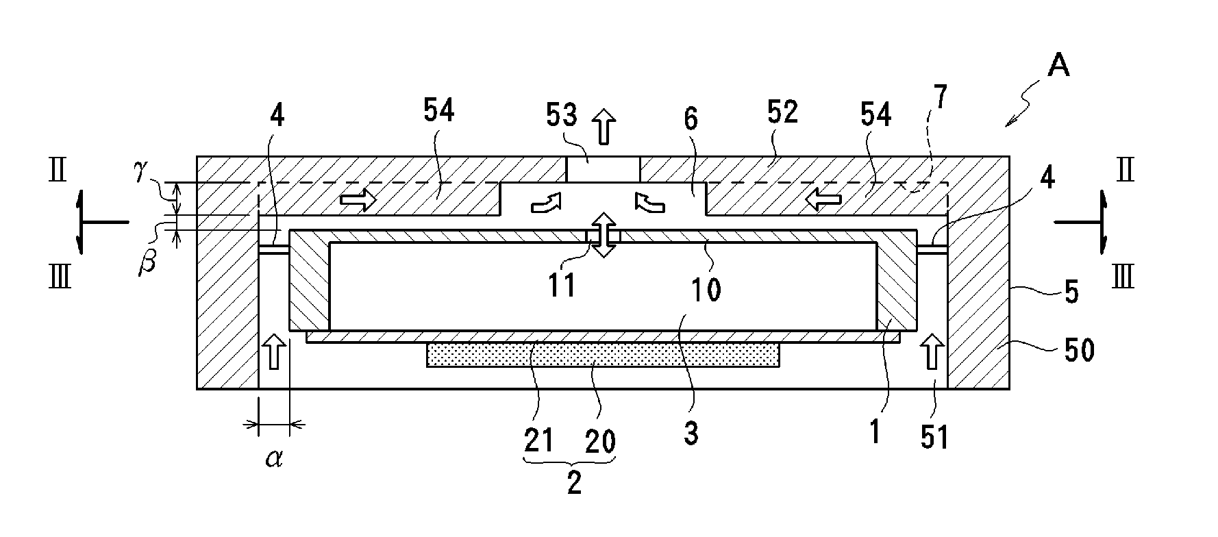
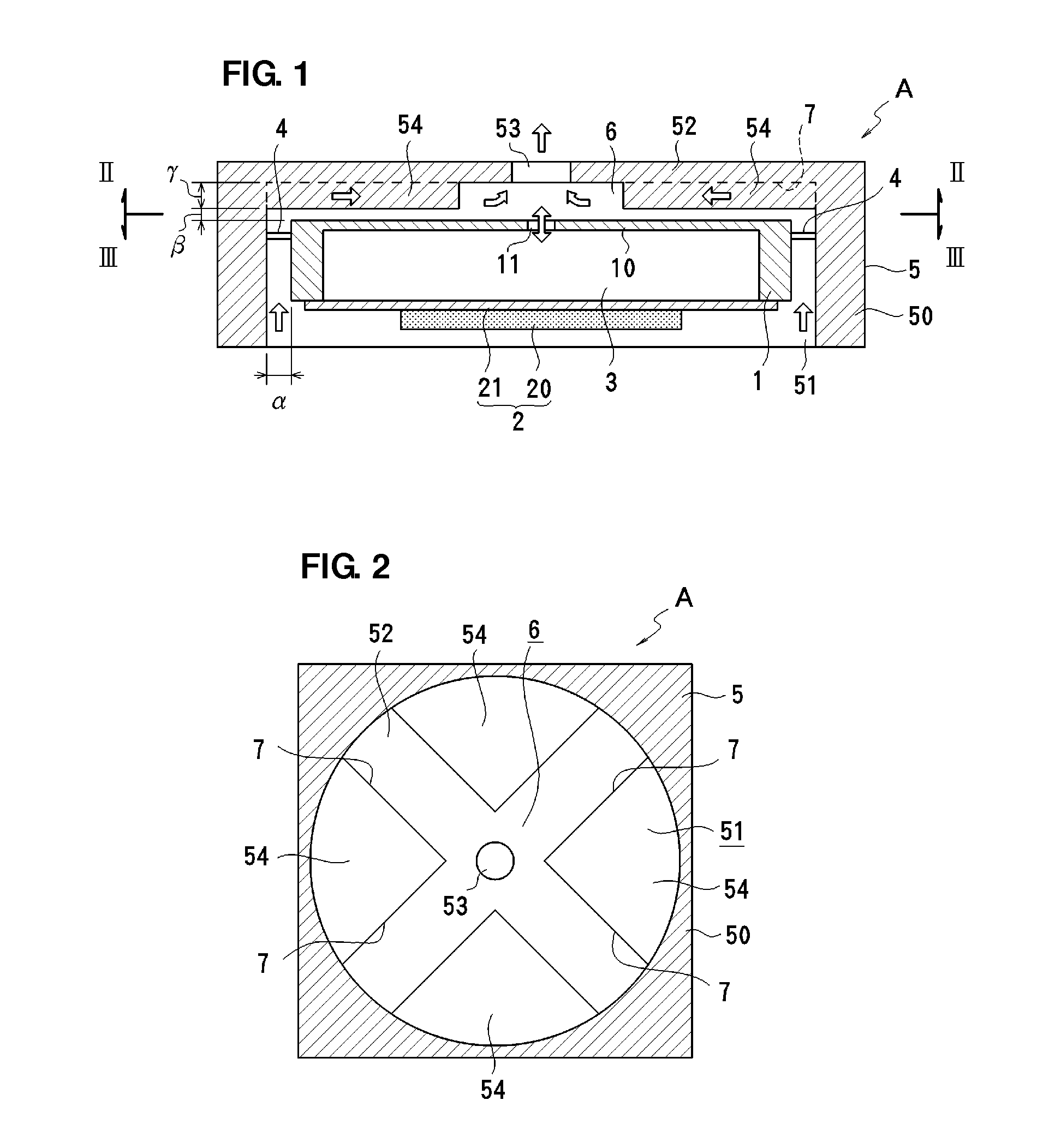
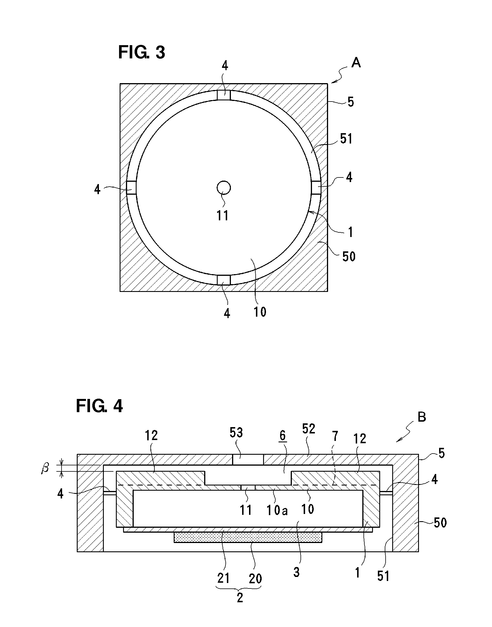
[0050]FIGS. 1 to 3 illustrate a piezoelectric micro-blower according to a first preferred embodiment of the present invention. The piezoelectric micro-blower is preferably used as an air blower for an electronic apparatus. The piezoelectric micro-blower A preferably includes an inner case 1 and an outer case 5 arranged to cover the outer periphery of the inner case 1 in a non-contact manner with a predetermined gap a provided therebetween. The inner case 1 and the outer case 5 are preferably connected to each other by a plurality of connecting portions 4. In the present preferred embodiment, as illustrated in FIG. 2, the outer case 5 preferably includes a side wall portion 50 and a top wall portion 52, and a cylindrical hollow section 51 that is open at the bottom is provided in the outer case 5. The inner case 1, which is preferably disc-shaped, for example, is disposed in the hollow section 51 such that the predetermined gap α is provided. The connecting portions 4 are provided be...

second preferred embodiment

[0057]FIG. 4 illustrates a piezoelectric micro-blower according to a second preferred embodiment of the present invention. In the piezoelectric micro-blower B according to the second preferred embodiment, components similar to those of the piezoelectric micro-blower A according to the first preferred embodiment are denoted by the same reference numerals and redundant descriptions thereof are omitted.

[0058]In the micro-blower B according to the second preferred embodiment, a projecting portion (peripheral wall portion) 12 that projects upward is preferably provided on a top surface of a top plate portion 10 of an inner case 1, and an inner surface of a top plate portion 52 of an outer case 5 is preferably flat or substantially flat, for example. Inflow passages 7 that extend radially are preferably provided in the projecting portion 12, for example. In this case, a portion of the top plate portion 10 of the inner case 1 other than a portion at which the projecting portion 12 is provi...

third preferred embodiment

[0079]FIGS. 13 and 14 illustrate a piezoelectric micro-blower according to a third preferred embodiment of the present invention. In the piezoelectric micro-blower C according to the third preferred embodiment, components similar to those of the piezoelectric micro-blowers A and B according to the first and second preferred embodiments are denoted by the same reference numerals, and redundant descriptions thereof are thus omitted.

[0080]In the micro-blower C according to the third preferred embodiment, a plurality of connecting portions 4 (preferably four connecting portions 4 in this preferred embodiment, for example) are provided on a top surface of a top plate 10 of an inner case 1 so as to extend vertically or substantially vertically. The top plate 10 is preferably fixed to a top plate of an outer case 5 using the connecting portions 4, for example. The connecting portions 4 may be defined by members that do not have spring elasticity, but are preferably defined by spring member...


PUM


Abstract

A piezoelectric micro-blower includes an inner case to which a peripheral portion of a vibrating plate including a piezoelectric element is fixed such that a blower chamber is defined between the inner case and the vibrating plate and an outer case arranged to cover an outer periphery of the inner case with a gap therebetween. The inner case is elastically retained in the outer case by a plurality of connecting portions. A first opening is provided in a top plate portion of the inner case that faces a central portion of the vibrating plate, and a second opening is provided in a top plate portion of the outer case that faces the first opening. A central space is provided between the top plate portions, and fluid introduced from the outside is guided to the central space through the gap between the inner and outer cases. The vibrating plate is driven in a bending mode so that air is sucked into the central space and is discharged through the second opening. The connecting portions prevent leakage of vibration of the vibrating plate from the inner case to the outer case, thereby reducing energy loss.

Description

BACKGROUND OF THE INVENTION[0001]1. Field of the Invention[0002]The present invention relates to a piezoelectric micro-blower arranged to convey compressible fluid, such as air.[0003]2. Description of the Related Art[0004]A piezoelectric micro-blower is known as an air blower for effectively dissipating heat generated in a housing of a portable electronic apparatus or for supplying oxygen required to generate electric power in a fuel cell. The piezoelectric micro-blower is a type of pump that includes a diaphragm that bends when a voltage is applied to a piezoelectric element, and is advantageous in that the piezoelectric micro-blower has a simple structure, small size and thickness, and low power consumption.[0005]Japanese Examined Patent Application Publication No. 64-2793 discloses a flow-generating apparatus including a base member that includes a compression chamber filled with fluid, a nozzle plate including a nozzle that faces the compression chamber, and a vibrator including...

Claims


Application Information

Patent Timeline
Patent Type & Authority Applications(United States)
IPC IPC(8): F04B35/04
CPCF04B43/046F04B45/047F04F7/00
Inventor FUJISAKI, MASAAKIKURIHARA, KIYOSHIKONDO, DAISUKE
Owner MURATA MFG CO LTD
Why Eureka
Try Eureka