
Spherical section hand splint

a hand splint and spherical section technology, applied in the field of hand splints, can solve problems such as poor hand mobility, and achieve the effect of simple construction and low cos

Inactive Publication Date: 2011-03-31
BROWN CHARLES L
View PDF9 Cites 2 Cited by
  • Summary
  • Abstract
  • Description
  • Claims
  • Application Information

AI Technical Summary

Benefits of technology

[0008]A principal object and advantage of the present invention is that the splint isolates the hand and palm in a natural at rest position.

Problems solved by technology

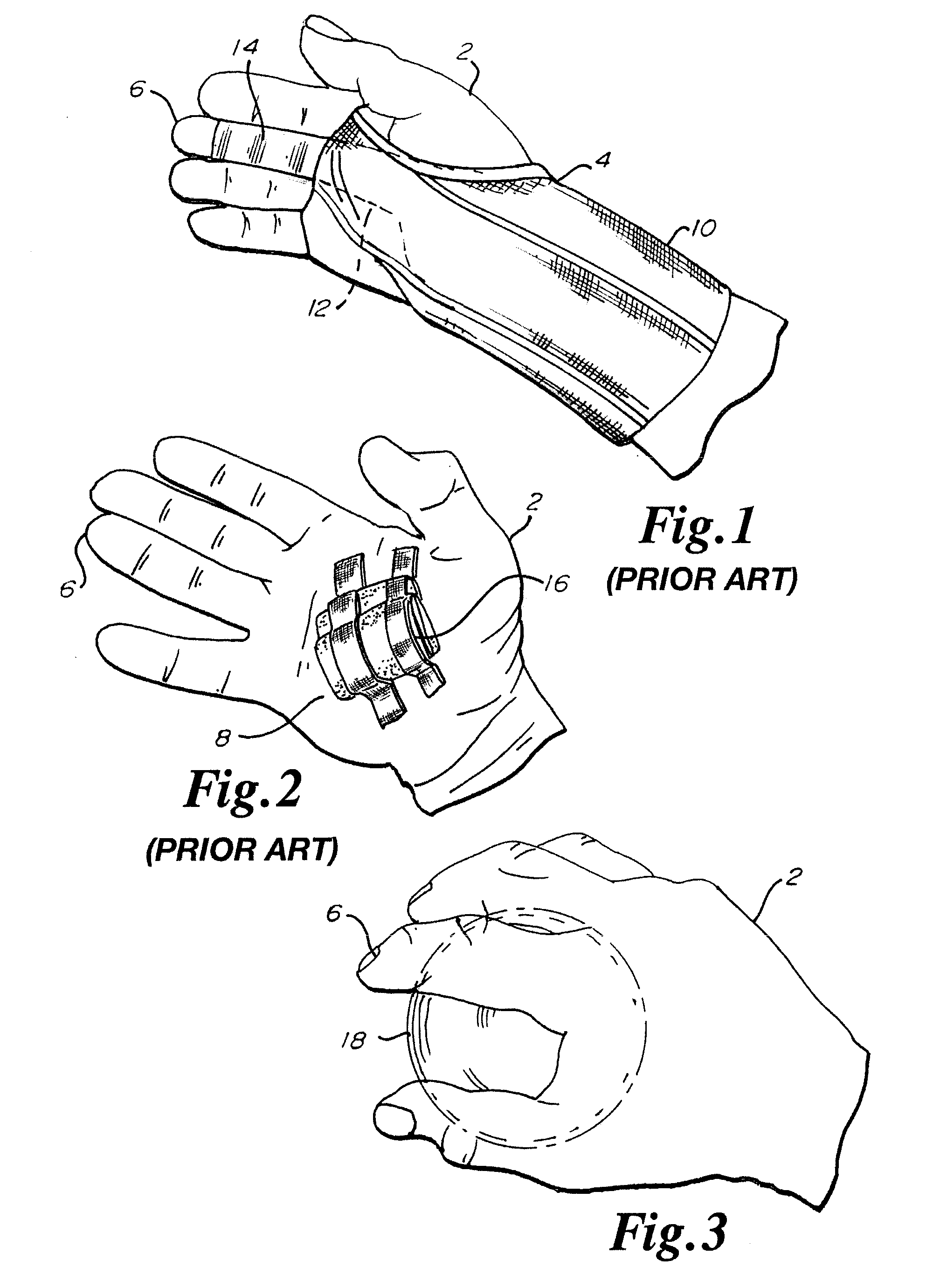
This prior art splint 10 is cumbersome to put on and take off and offers poor hand mobility beyond the necessary immobilization of the injured anatomical part of the hand 2.

Method used


Image

  • Spherical section hand splint
  • Spherical section hand splint
  • Spherical section hand splint

Examples


Embodiment Construction

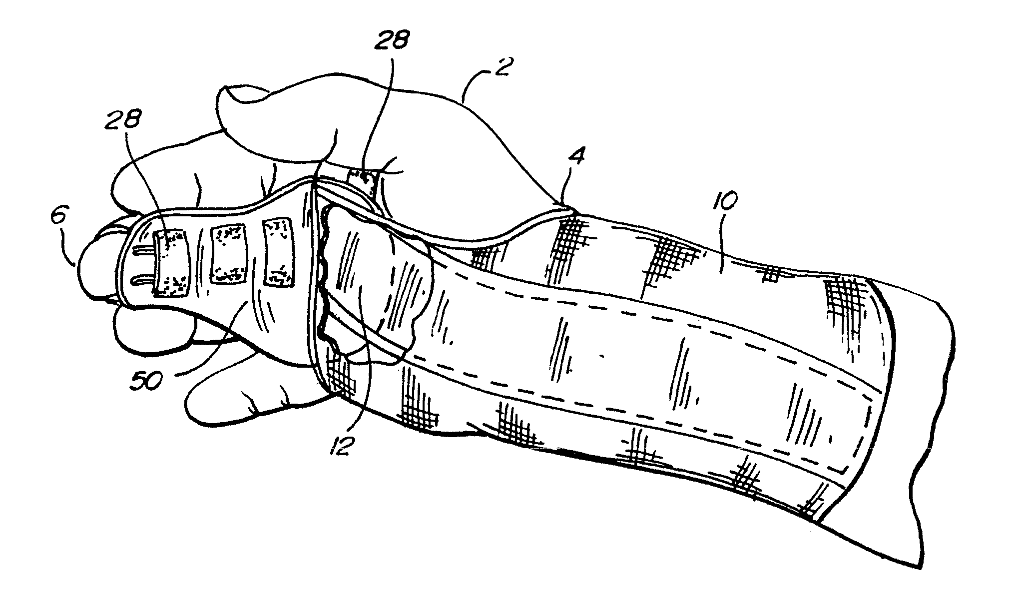
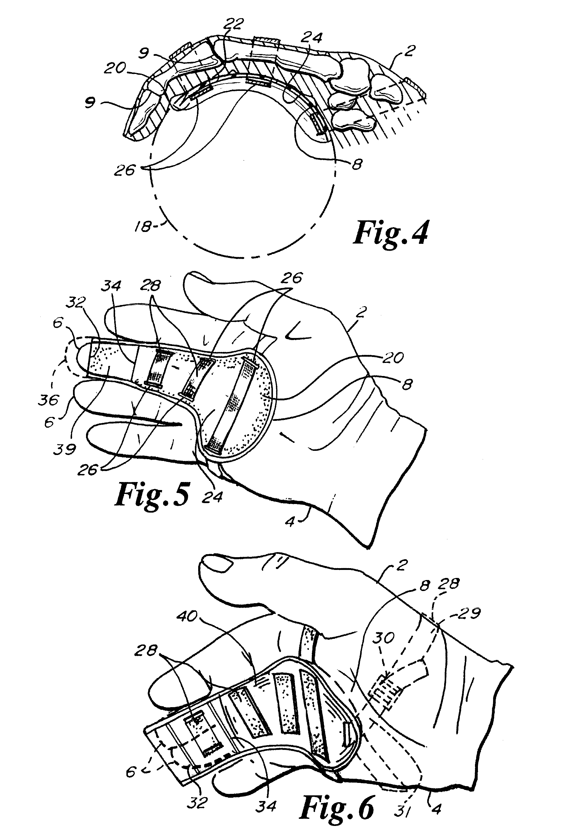
[0027]Referring to FIGS. 1 through 9, the hand 2 generally includes a wrist 4, fingers 6 and palm 8. The spherical hand splint 20 of the present invention may be viewed in FIGS. 4, 5, and 8. This splint 20 has its spherical section portion extending underneath a finger 6 to support and immobilize the finger 6 which further immobilizes injured or inflamed ligaments, tendons or knuckles 9 associated with injured fingers 6.

[0028]This spherical section hand splint 20 generally includes a concave palm surface 22 which fits up against a palm 8 of the hand 2. A convex exposed outer surface 24 faces outwardly from the palm 8. The splint 20 suitably has slots 26 therethrough to allow one end 29 of straps 28 with hook and loop surfaces to pass through slot 26, D-ring or buckle 30 of the other end 31 of the strap 28 and to lay back upon the strap 28 connecting a hook and loop surfaces. Alternatively, for short expanses, such and for securing fingers 6, the splint 20, the D-ring or buckle is no...


PUM


Abstract

A flexible, low profile hand splint includes a section of a hollow sphere or ball that comfortably puts the hand in an at rest natural position, while immobilizing one or more anatomical hand parts with extended spherical sections thereby immobilizing fingers, knuckles and tendons. Straps hold the splint onto the palm and immobilize one or more of the fingers. An inverse version of the splint provides protection to the injured soft tissue of a palm.

Description

CROSS-REFERENCE TO RELATED APPLICATION[0001]The present application is based on and claims the benefit of U.S. provisional patent application Ser. No. 61 / 427,333, filed Sep. 30, 2009.BACKGROUND OF THE INVENTION[0002]This invention relates to a hand splint for initial injury care and to support healing of an injury and more particularly to a spherical section hand splint that puts all or part of the hand into a natural hand at rest position to immobilize injured anatomical parts of the hand.[0003]The anatomical parts of the hand are subject to many different types of injuries, not limited to, but including, finger fractures, finger joint dislocations, tendon dislocations, finger and knuckle joint injuries, finger crush injuries, finger soft tissue injuries, incomplete tendon lacerations, sprains from jammed fingers, finger alignment injuries, finger and knuckle pain control issues, tendon repairs, laceration repairs, skin graphs, soft tissue injuries and acutely inflamed arthritic jo...

Claims


Application Information

Patent Timeline
Patent Type & Authority Applications(United States)
IPC IPC(8): A61F5/04
CPCA61F5/0118
Inventor BROWN, CHARLES L.
Owner BROWN CHARLES L
Learn More