
Network graph evolution rule generation

Active Publication Date: 2011-03-31
R2 SOLUTIONS
View PDF2 Cites 25 Cited by
  • Summary
  • Abstract
  • Description
  • Claims
  • Application Information

AI Technical Summary

Benefits of technology

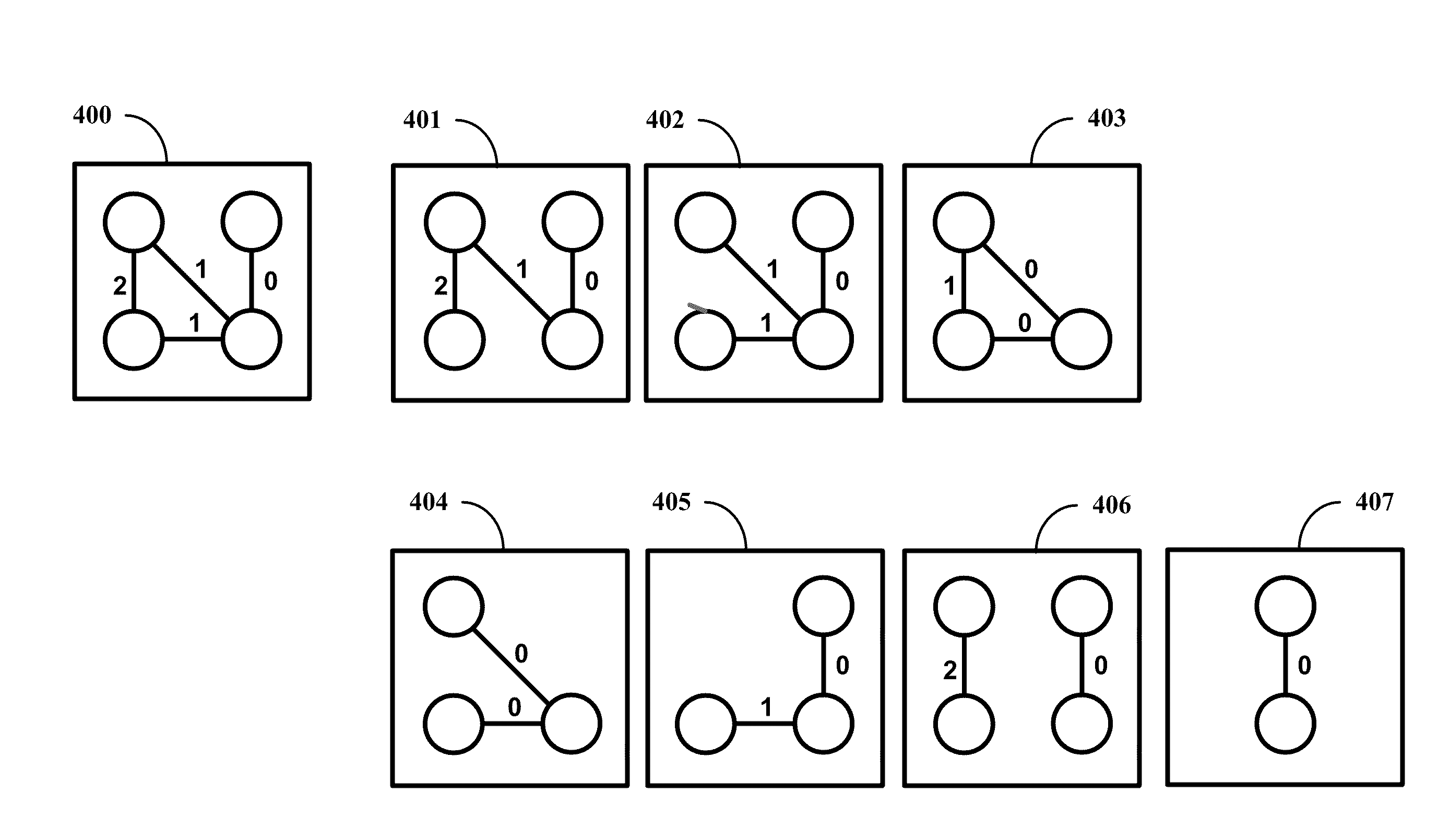
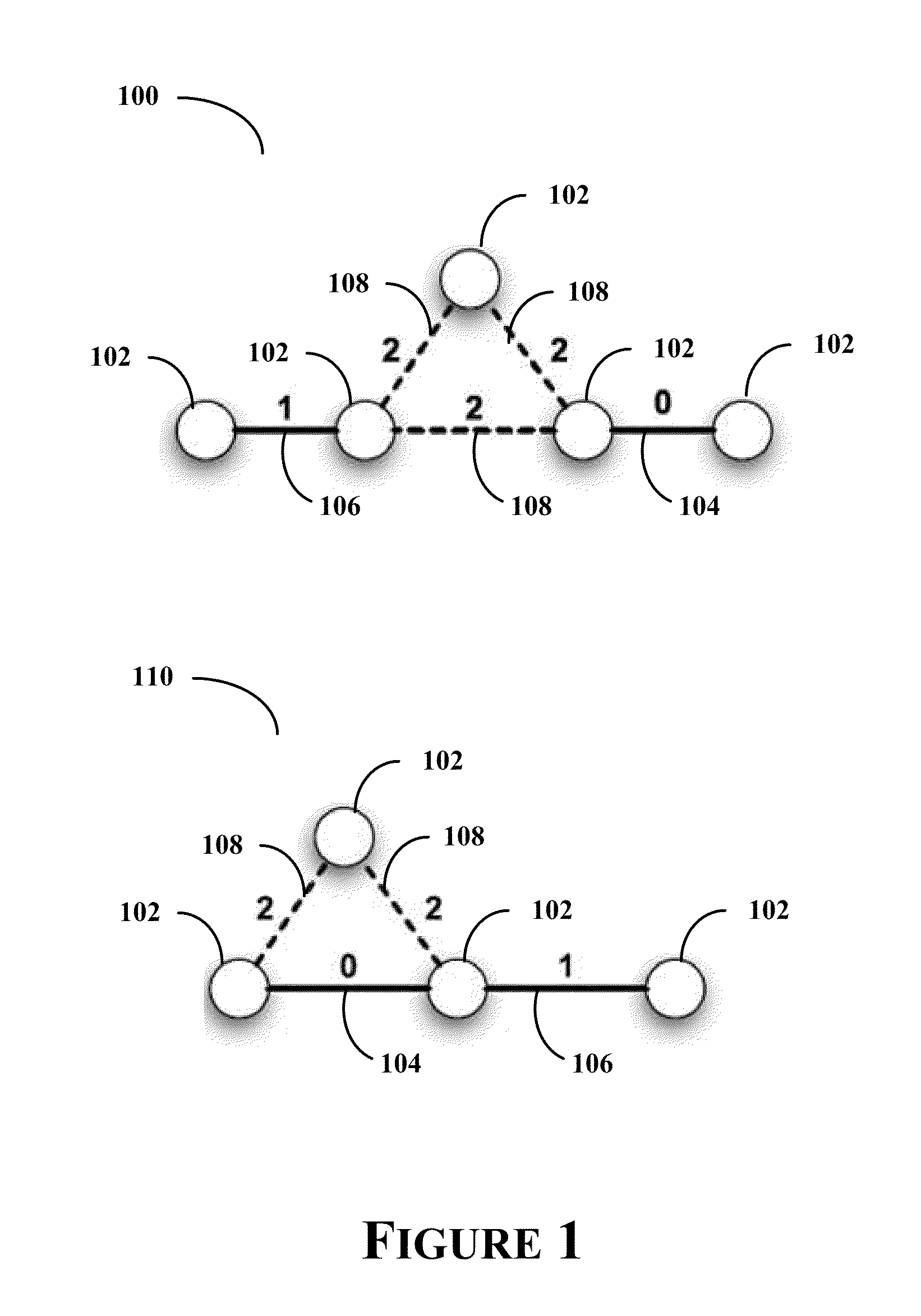
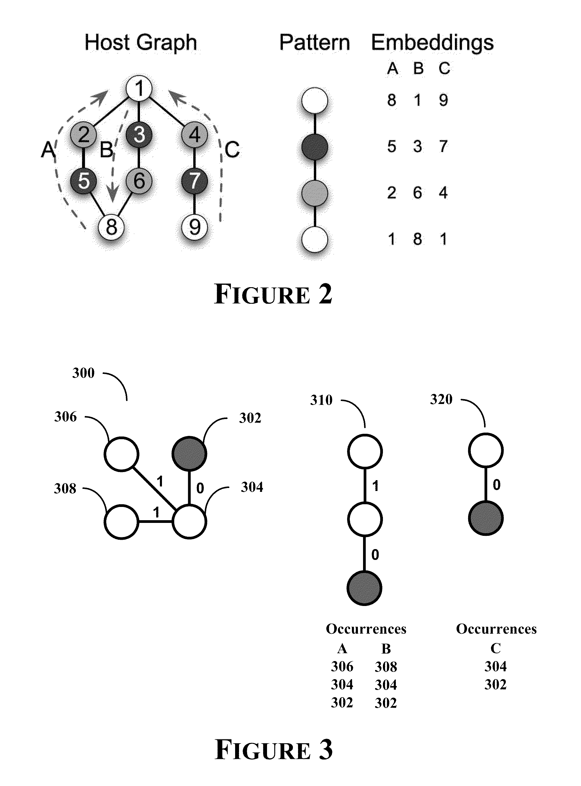
[0004]The present disclosure seeks to address failings in the art and to provide a system, method and apparatus of analyzing temporal evolution of a social network. In accordance with one or more embodiments, a network's evolution is characterized by graph evolution rules

Problems solved by technology

Social networks can be quite complex, and analysis of a social network, or networks, can consume considerable computational resources.

Method used


Image

  • Network graph evolution rule generation
  • Network graph evolution rule generation
  • Network graph evolution rule generation

Examples


Embodiment Construction

[0019]In general, the present disclosure includes a graph evolution rule generation system, method and architecture.

[0020]Certain embodiments of the present disclosure will now be discussed with reference to the aforementioned figures, wherein like reference numerals refer to like components. Embodiments disclose herein may be described with reference to a social network; however, it should be apparent that the embodiments are not limited to a social network, and that the embodiments can be applied to any network that can change over time.

[0021]In accordance with one or more embodiments, a network is expressed in terms of a graph, which comprises nodes and edges. Using a more formalistic expression, a graph, G, over a set of nodes, V, and edges, E, with a labeling function used to assign labels to nodes and edges, can be expressed as:

[0022]G=(V,E, λ) is used to denote a graph G over a set of nodes V and a set of edges, E⊂ V×V, with a labeling function λ:V∪E→Σ, assigning labels to no...


PUM


Abstract

A network's evolution is characterized by graph evolution rules. A graph that represents an evolutionary network is mined to identify evolutional patterns of the network, and graph evolution rules are generated using identified evolutional patterns. The generated graph evolution rules represent the evolutional patterns of the network.

Description

FIELD OF THE DISCLOSURE[0001]The present disclosure relates to characterization of a network's evolution, such as a characterization of an evolution of a social network using graph evolution rules, and more particularly to mining a graph that represents an evolutionary network to identify evolutional patterns, and using identified evolutional patterns to generate graph evolution rules, which represent the evolutional patterns of the network.BACKGROUND[0002]A social network has been described as a social structure of relationships or bonds between individuals, and / or groups of individuals, such as societies. The social structure can be said to be made of individuals (or organizations) called “nodes,” which are connected, or related, in some manner.[0003]The social structure can be expressed using conventional network terms, such as nodes and edges, where nodes are entities, such as individuals, groups, etc., and edges, or ties, represent relationships between entities. Social network...

Claims


Application Information

Patent Timeline
IPC IPC(8): G06F17/30
CPCH04L43/045G06Q10/10G06F16/26G06F16/128G06F16/211G06F16/258G06F16/288G06F16/2477G06F16/9024
Inventor BONCHI, FRANCESCOGIONIS, ARISTIDESBERLINGERIO, MICHELEBRINGMANN, BJORN
Owner R2 SOLUTIONS
Learn More