Frame Boundary Detection and Synchronization System for Data Stream Received by Ethernet Forward Error Correction Layer

a synchronization system and data stream technology, applied in the field of data processing system, can solve problems such as inability to detect frames, increase hardware overhead, and improve frame boundary detection speed, and achieve fast frame synchronization. , the effect of increasing only a few hardware overhead

Inactive Publication Date: 2011-03-31
IBM CORP
View PDF4 Cites 11 Cited by
  • Summary
  • Abstract
  • Description
  • Claims
  • Application Information

AI Technical Summary

Benefits of technology

[0020]Different from the above method as described in IEEE 802.3ap-2007 Criterion, the claimed method optimizes a frame boundary detection system for a data stream received by an Ethernet Forward Error Correction layer as well as a frame synchronization system for the data stream of the Forward Error Correction laye

Problems solved by technology

Disadvantages of the general method are that a detection procedure for one time can only

Method used


Image

  • Frame Boundary Detection and Synchronization System for Data Stream Received by Ethernet Forward Error Correction Layer
  • Frame Boundary Detection and Synchronization System for Data Stream Received by Ethernet Forward Error Correction Layer
  • Frame Boundary Detection and Synchronization System for Data Stream Received by Ethernet Forward Error Correction Layer

Examples


Embodiment Construction

[0046]The preferred embodiments of the present invention will be described in more details with reference to the attached drawings in which the preferred embodiments of the invention are shown. However, the invention can be implemented in various forms and should not be comprehended to be limited to the embodiments explained here. Instead, these embodiments are provided in order to make the invention more thorough and integral and completely convey the scope of the invention to those skilled in the art.

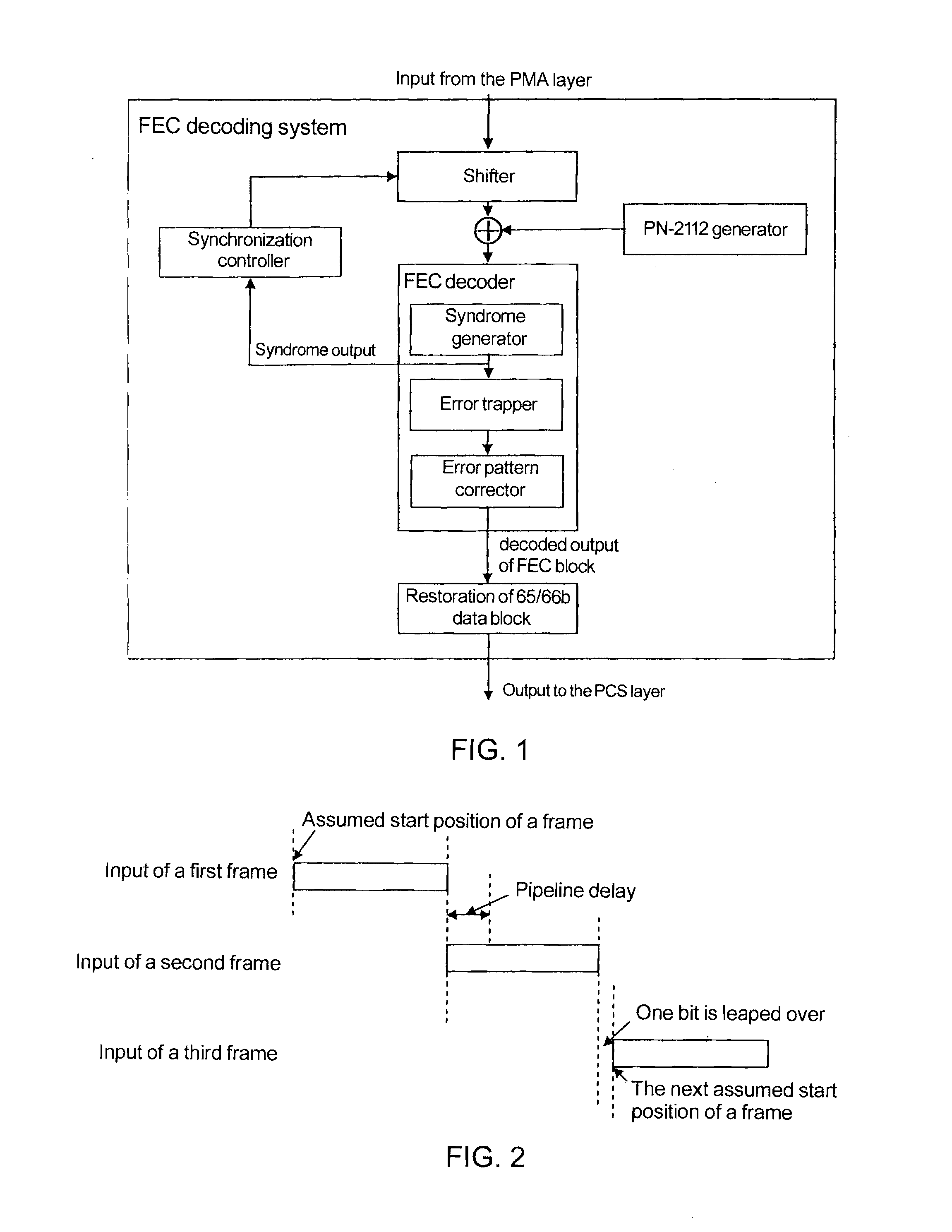
[0047]In a prior art scheme, due to the presence of a pipeline structure in a hardware, when a method of leaping over a position of one bit is employed, only one frame boundary can be detected and nearly a half of frames are discarded, which prolongs the frame boundary detection time and slows the frame synchronization speed.

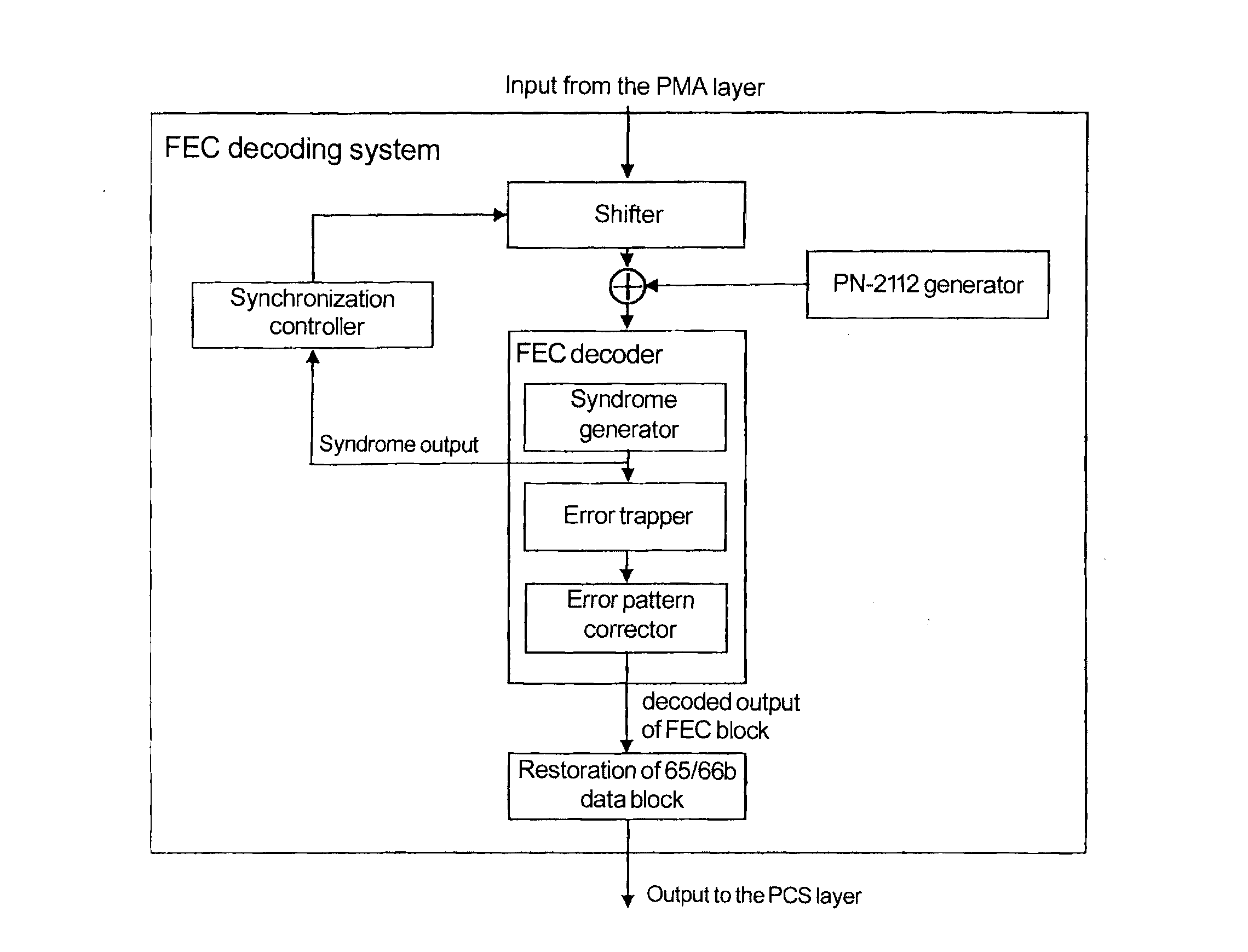
[0048]The present invention optimizes the structure of an FEC decoder at a reception terminal, thus speeding up the frame synchronization procedure. Specifically,...


PUM


Abstract

The present invention discloses a frame boundary detection system and a synchronization system for a data stream received by an Ethernet Forward Error Correction layer. The frame boundary detection system includes a shifter, two descramblers, a syndrome generator and trapper. The error trapper includes a big-little endian mode controller for controlling the big-little endian conversion of the error trapper. If the error trapper operates in the big endian mode, the error trapper implements the function of the syndrome generator, operates at the same time with the syndrome generator, and performs a second FEC check, wherein when the shifter performs the FEC check by intercepting data with a length of one frame plus A bits, two start positions of the frame can be verified, where A is a positive integer less than a length of one frame. The invention can improve the frame boundary detection speed and the frame synchronization speed, and increase only a few hardware overheads.

Description

TECHNICAL FIELD[0001]The present invention generally relates to a data processing system, and specifically to a frame boundary detection system and synchronization system for a data stream received by an Ethernet Forward Error Correction layer.BACKGROUND[0002]The Chapter 74 of IEEE802.3ap-2007, the latest version of which is IEEE 802.3-2008, and IEEEP802.3D1.2 define an FEC (Forward Error Correction) sublayer applied to a BASE-R physical layer of 10G Ethernet. The criterion of the FEC sublayer reduces the BER rate of a system from 10−7 to 10−12. Also, this criterion is applicable to applications of 40G / 100G Ethernet.[0003]In order to be compatible with different Ethernet application layers, protocols provide that the FEC layer compresses an original frame header to leave space so as to load an FEC check bit, thus assuring that the layer keeps the same frame length (the frame length defined in the Chapter 74 of IEEE 802.3ap-2007 is 2112 bits) as other application layers. However, suc...

Claims


Application Information

Patent Timeline
IPC IPC(8): H03M13/15G06F11/10
CPCH03M13/159H03M13/33H04L7/048H03M13/6561H04L1/0047H03M13/333
Inventor HE, YINLIN, YI FANLIU, YANGYANG, HAO
Owner IBM CORP
Why Eureka
Try Eureka