Fuel filler system

a fuel supply nozzle and fuel filler technology, applied in liquid handling, packaging goods types, transportation and packaging, etc., can solve the problems of no international standards for fuel supply nozzles, no fuel supply nozzles, water vapor may condense and collect near the sealing door, etc., to achieve the effect of minimal effort and cost, and minimal risk of system and/or vehicle damag

Inactive Publication Date: 2011-04-07
FORD GLOBAL TECH LLC
View PDF28 Cites 52 Cited by
  • Summary
  • Abstract
  • Description
  • Claims
  • Application Information

AI Technical Summary

Benefits of technology

[0021]An advantage of the present invention is that the vehicle can travel through the assembly process with only the lower piece of the fuel assembly attached. Because the lower piece has a flapper door, debris is prevented from entering the fuel tank. But, fuel can be supplied to the vehicle through the flapper door.
[0022]Yet another advantage of the present development is that if the upper piece of the fuel assembly needs to be replaced, for example by virtue of damage caused, for example, by vandalism or by the vehicle owner moving among regions with different fuel supply nozzle diameters, the entire fuel filler system need not be replaced. Instead, the existing upper piece of the fuel filler assembly can be decoupled from the lower piece and an appropriate replacement upper piece is coupled with the lower piece. In embodiments in which the lower and upper pieces can be decoupled nondestructibly, the replacement can be accomplished with minimal effort and cost and with minimal risk of destruction to the system and / or vehicle. In another embodiment, the upper piece is destroyed in the process of removal to avoid the possibility that it could be installed onto another vehicle for which it is not intended. In such an embodiment, the lower piece is unharmed in the process so that it can couple with a replacement upper piece of the appropriate specification for the region in which its operation is intended.

Problems solved by technology

Also, water vapor may condense and collect near the sealing door.
It is also known that when fueling a vehicle some fuel drips off of the fuel filler nozzle when withdrawing the nozzle from the fuel filler system.
Another issue related to fuel filler pipes is to prevent misfueling.
However, the reverse is not prevented by this measure alone.
There are no international standards on fuel supply nozzles.
On a global basis, fuel supply nozzle diameter depends on both the type of fuel being dispensed and the geographic region, thereby further complicating the issue of misfueling.
However, it doesn't prevent water vapor from entering the upper door and condensing in the space between the two doors or from fuel vapors trapped between the two doors from vaporizing and exiting out the non-sealing upper door.

Method used


Image

  • Fuel filler system
  • Fuel filler system
  • Fuel filler system

Examples


Embodiment Construction

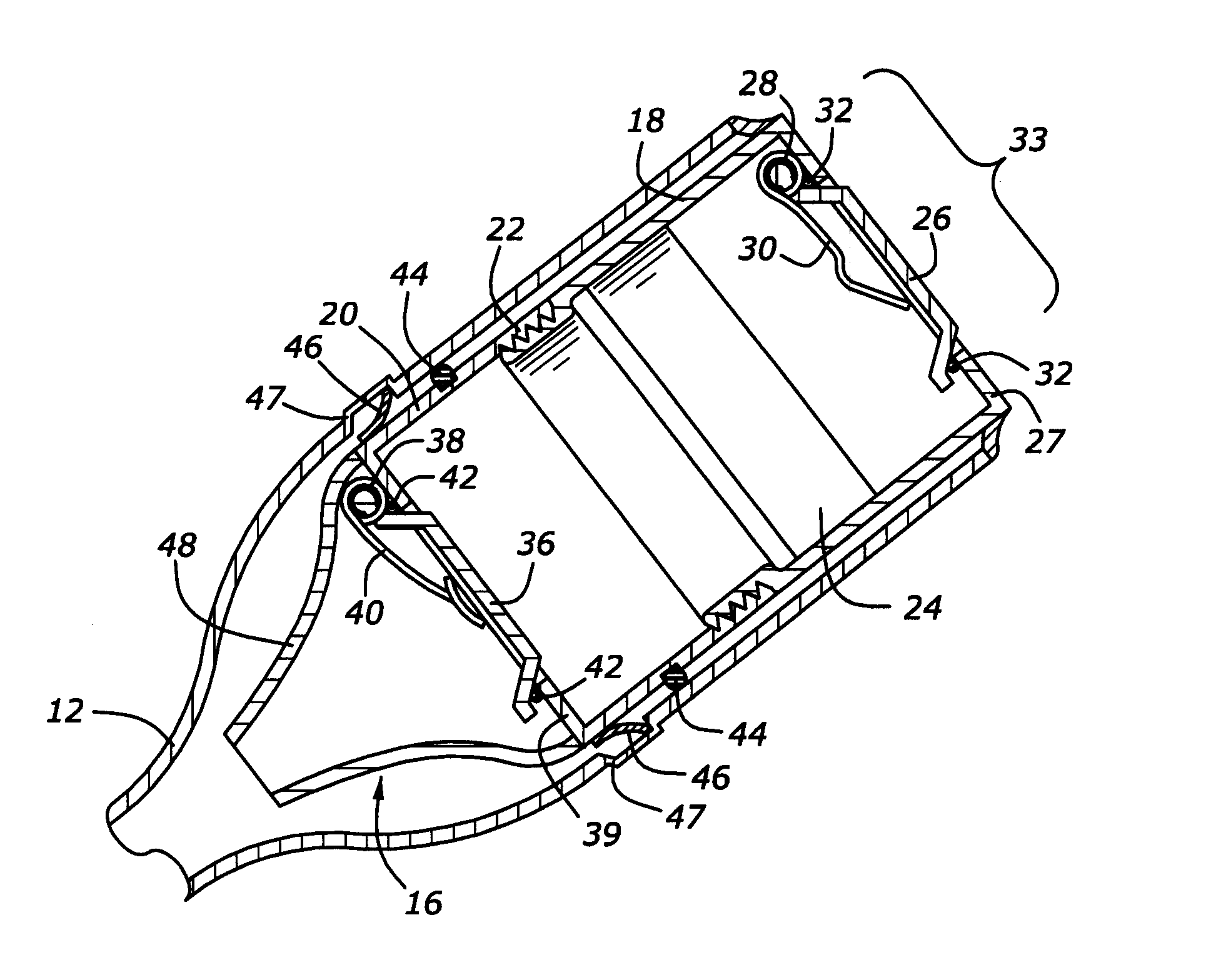
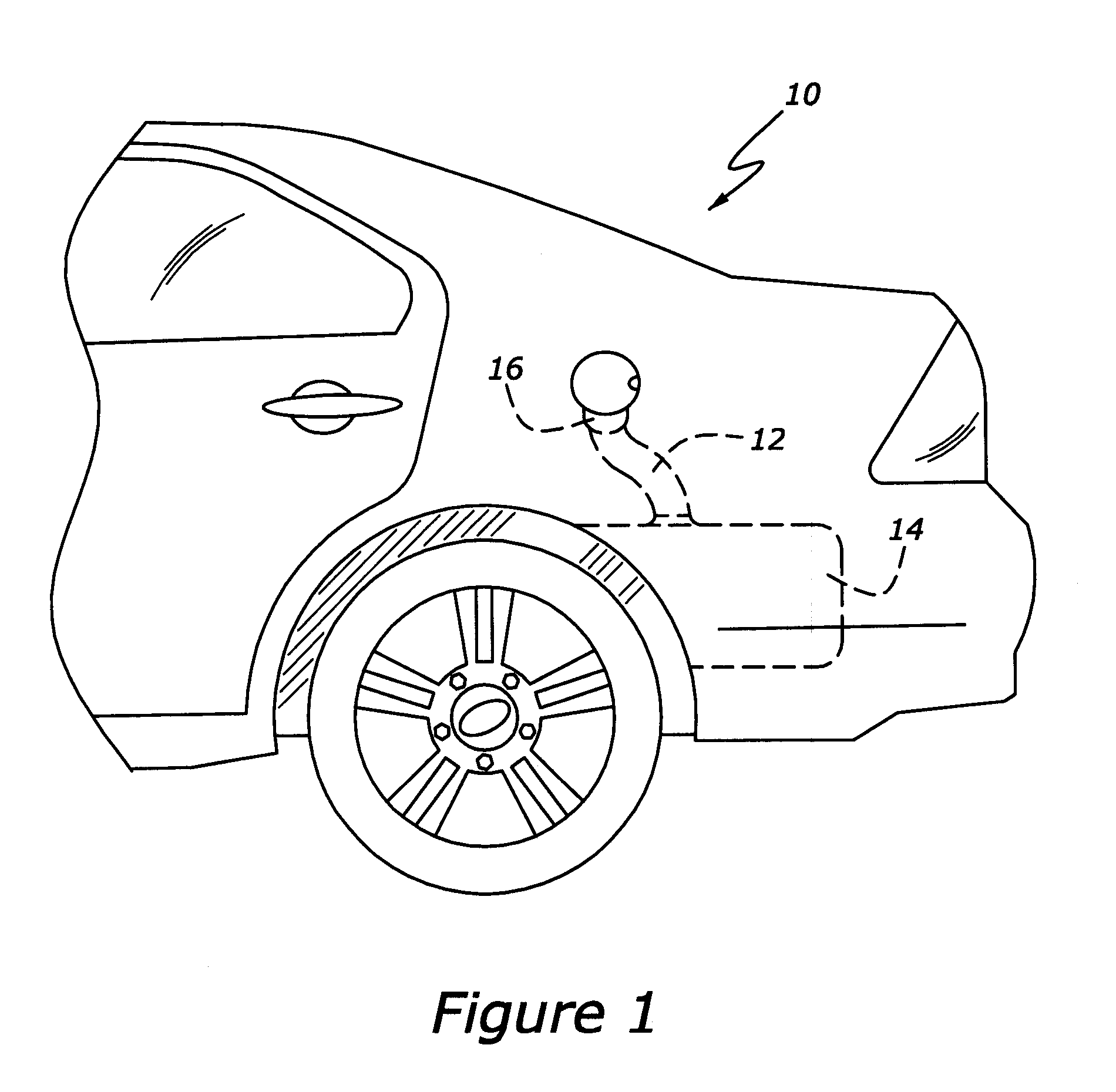
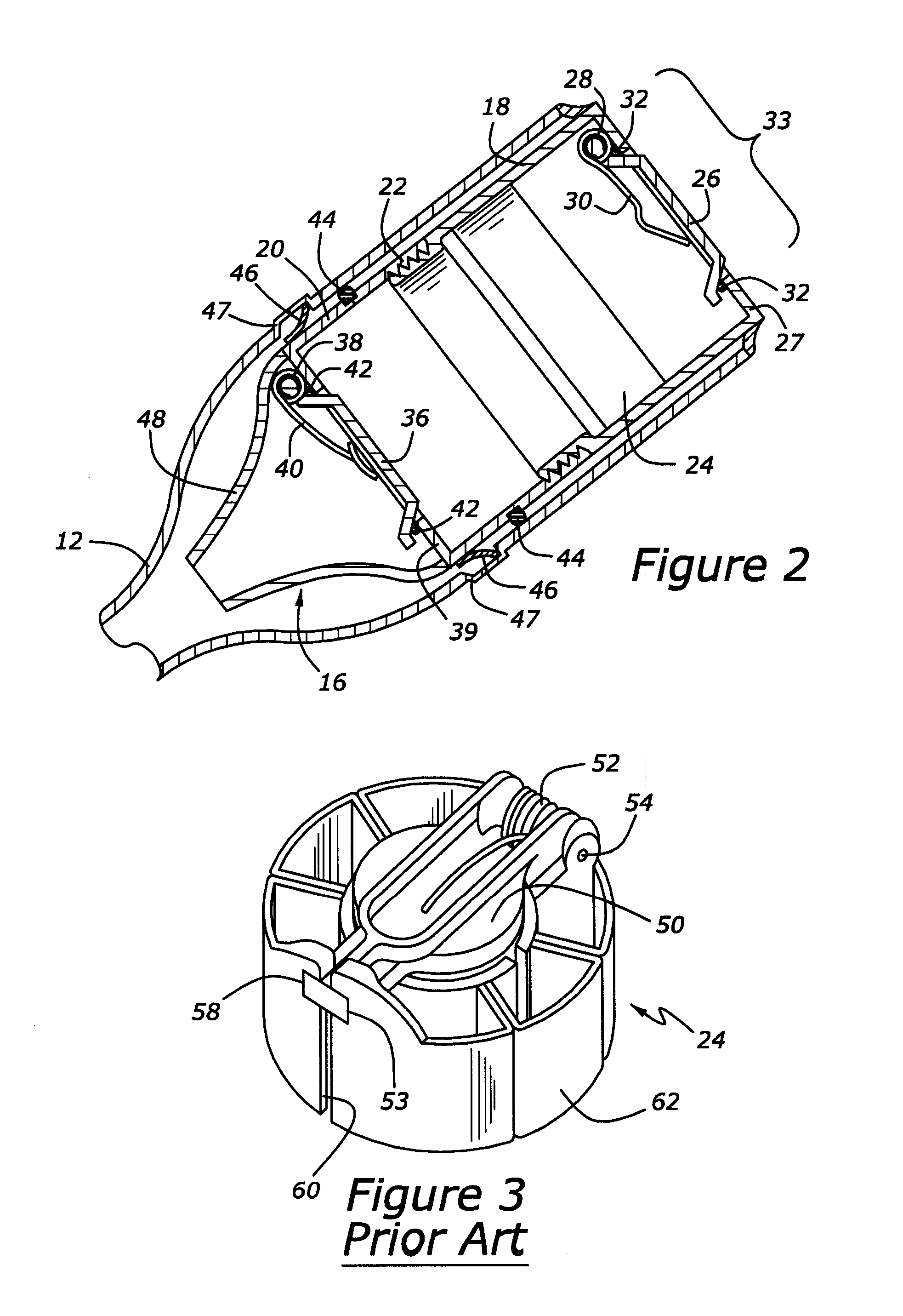
[0034]As those of ordinary skill in the art will understand, various features of the embodiments illustrated and described with reference to any one of the Figures may be combined with features illustrated in one or more other Figures to produce alternative embodiments that are not explicitly illustrated or described. The combinations of features illustrated provide representative embodiments for typical applications. However, various combinations and modifications of the features consistent with the teachings of the present disclosure may be desired for particular applications or implementations. The representative embodiments used in the illustrations relate generally to a capless fuel fill assembly for an automotive vehicle. However, the fuel fill assembly may be incorporated into various other types of vehicles, such as boats, private airplanes, etc. Those of ordinary skill in the art may recognize similar applications or implementations whether or not explicitly described or il...


PUM

PropertyMeasurementUnit
forceaaaaaaaaaa
diameteraaaaaaaaaa
pressureaaaaaaaaaa

Abstract

A capless fuel filler system has lower and upper sealing doors. The upper sealing door prevents water, water vapor, dust, etc. from entering into the space between the lower and upper doors. In prior systems with one sealing door a drain is provided to remove water (either directly entering or condensed water vapor), dust, or excess fuel drips from fueling just upstream of the lower door. By providing two sealing doors, water and dust cannot access the lower door. Although some fuel may puddle upstream of the lower door after a fueling event, the fuel is trapped, with no drain to the exterior, between lower and upper doors. If such fuel evaporates, it causes the lower door to open and vents the fuel vapors to the fuel tank, a desirable disposition for the vapors. The two sealing doors are contained in separate components to facilitate interchangeability and serviceability.

Description

BACKGROUND[0001]1. Technical Field[0002]The present development relates to a fuel filler assembly for an automotive vehicle.[0003]2. Background Art[0004]Capless fuel filler systems are known to provide a sealing door through which a fuel supply nozzle can be inserted for fueling purposes. The upstream side of the sealing door is subjected to ambient conditions. Water may splash up from the vehicle and collect at the upstream side of the sealing door. Also, water vapor may condense and collect near the sealing door. To prevent the collection of water and then entry of the water into the fuel tank during subsequent fueling, a drain is provided to drain away the fluid to a benign location.[0005]It is also known that when fueling a vehicle some fuel drips off of the fuel filler nozzle when withdrawing the nozzle from the fuel filler system. In the prior art, this fuel collected on the upstream side of the sealing door is also drained away with the same drain.[0006]It is desirable to eli...

Claims


Application Information

Patent Timeline
Patent Type & Authority Applications(United States)
IPC IPC(8): B60K15/04
CPCB60K15/0406B60K2015/0445B60K2015/0429B60K2015/0419
Inventor BEIER, ROBERT JOSEPHAITKEN, BRIAN THOMASGINSTER, MICHAEL PETERRANGER, JOHNWOHLFAHRTER, MICHAELSANDHU, RAKESH
Owner FORD GLOBAL TECH LLC
Why Eureka
Try Eureka