
Terminal Box

Active Publication Date: 2011-04-07
HOSIDEN CORP
View PDF15 Cites 20 Cited by
  • Summary
  • Abstract
  • Description
  • Claims
  • Application Information

AI Technical Summary

Benefits of technology

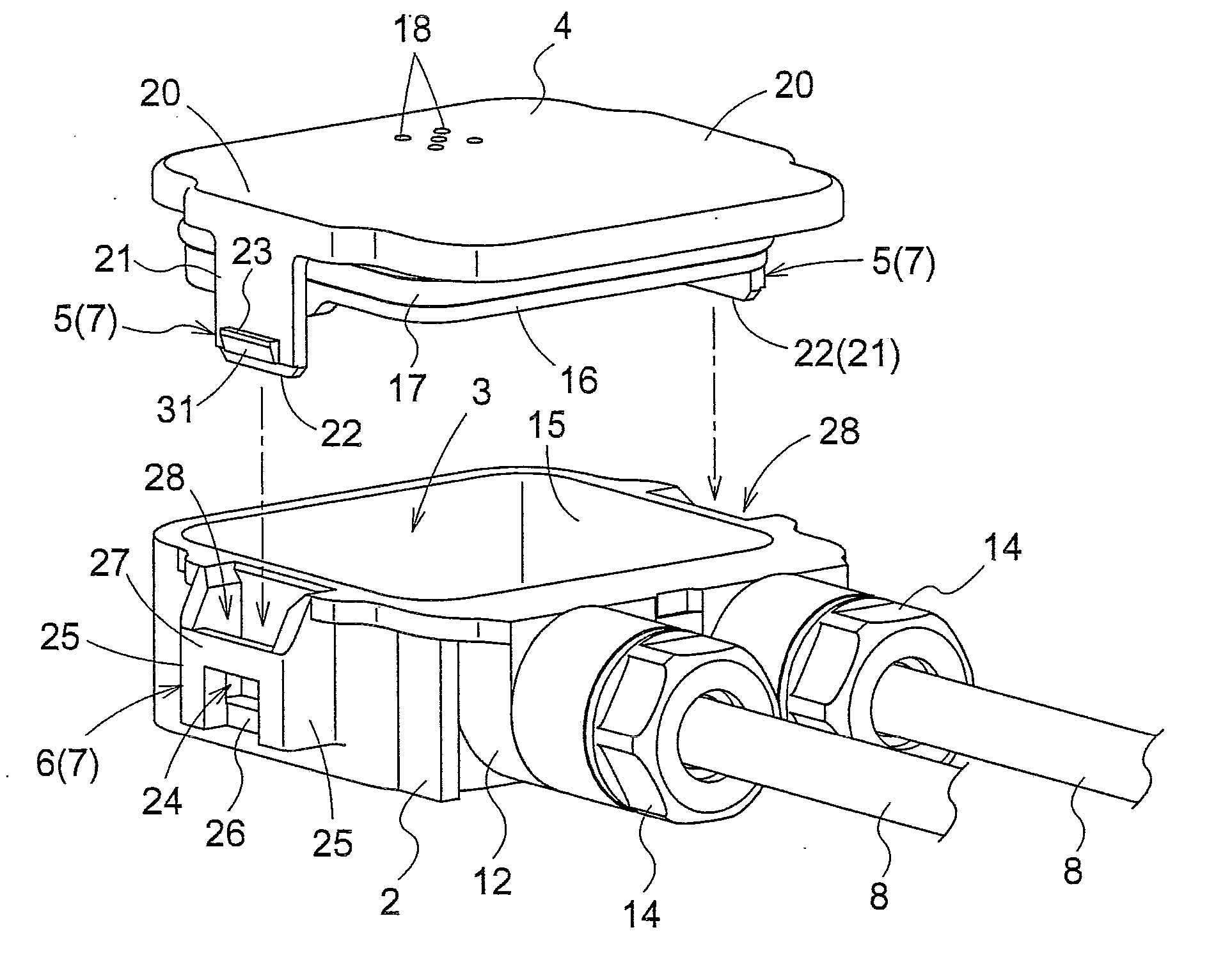
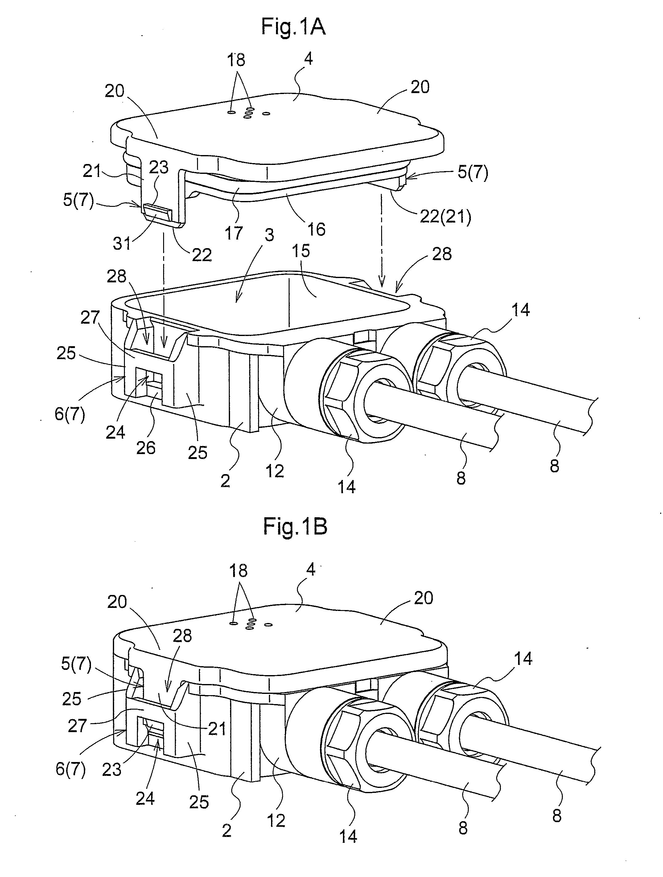
[0017]With this arrangement, the engaging element includes the projecting piece extending in the pressing direction of the lid member, and the engaging pawl extending in the direction vertical to the extending direction of the projecting piece and provided in part of the projecting piece other than the distal end portion of the projecting piece, while the engaged element has the receiving hole opening toward the outer side of the box casing and allowing the distal end portion of the projecting piece to be exposed to the outside when engaged with the engaging pawl. Thus, the terminal box with this arrangement allows the distal end portion of the projecting piece to be pressed toward the disengagement side and moved toward the direction opposite from the pressing direction of the lid member with the control member inserted into the receiving hole from the outer side of the box casing. More particularly, the operation of disengaging the engaging element from the engaged element and the operation of moving the lid member in the direction opposite from its pressing direction can be performed with continuous operations using a single control member. This simplifies the operations for removing the lid member from the box casing.
[0021]This arrangement can restrict displacement of the projecting piece caused when the distal end portion of the projecting piece is pressed, and reduce the possibility that the projecting piece is deformed. Thus, the lid member removed from the box casing is adequately reusable. Preferably, the restricting portion is provided in the box casing.
[0023]With this arrangement, the engaging pawl does not project outward of the inner wall surface of the receiving hole. Thus, it is prevented that the engaging pawl is caught by any other element and inadvertently disengaged from the receiving hole.

Problems solved by technology

According to the device disclosed in Japanese Patent No. 3014628, it is not possible to move the lid member in the direction opposite from its pressing direction only by disengaging the engaging element form the engaged element.
In this way, the conventional art has a drawback that the operations become complicated in removing the lid member from the box casing.
Thus, the conventional art has a further drawback that the lid member removed from the box casing is not reusable.

Method used


Image

  • Terminal Box
  • Terminal Box
  • Terminal Box

Examples


Embodiment Construction

[0037]An embodiment of the present invention will be described hereinafter in reference to the accompanying drawings.

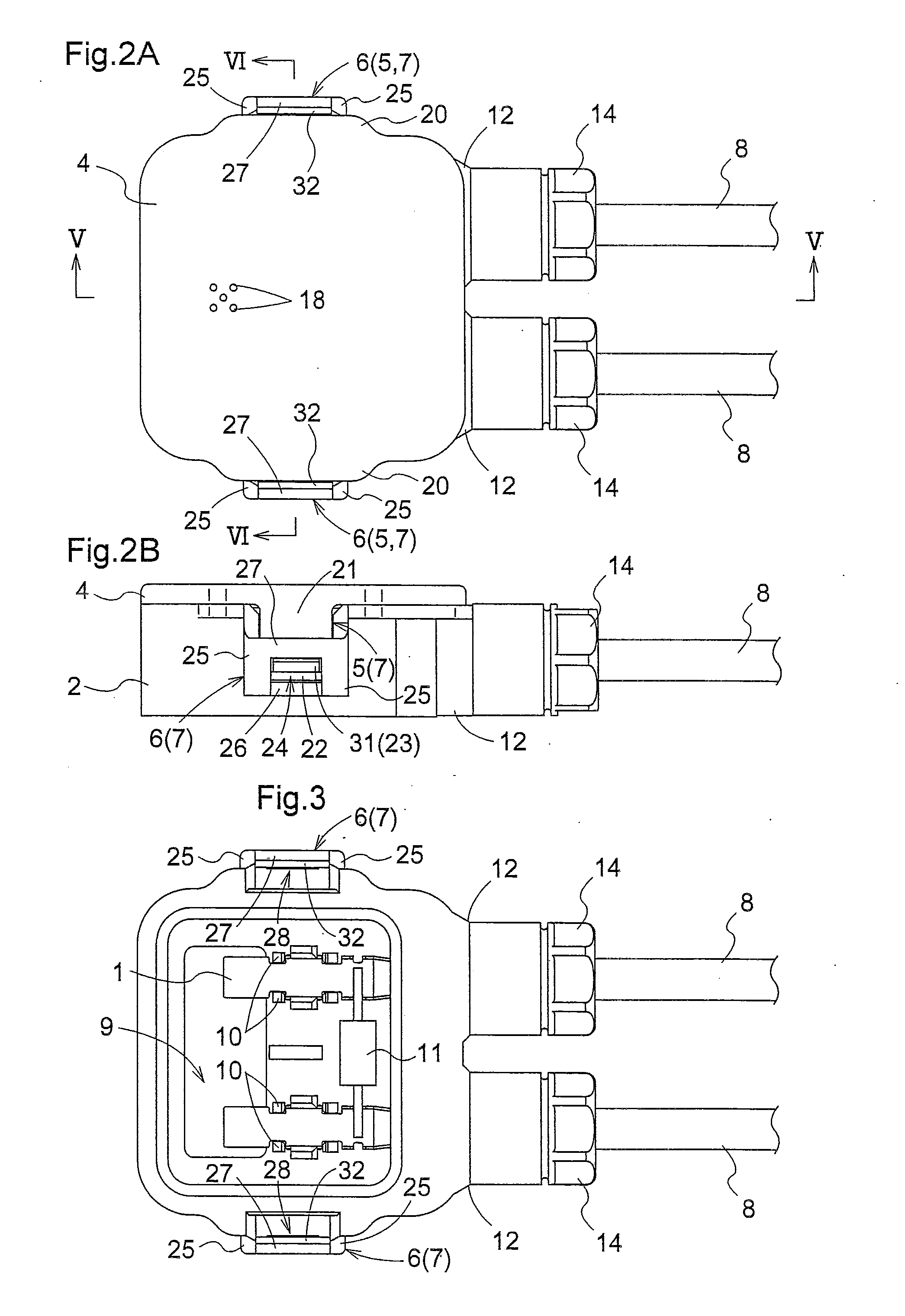
[0038]FIGS. 1 and 2 show a terminal box for a solar cell module in accordance with the present invention. The terminal box comprises a box casing 2 made of resin including a pair of metal terminal elements 1 (see FIG. 3) incorporated into the interior of the casing, a lid element 4 made of resin for closing an opening 3 of the box casing 2, and an engaging mechanism 7 for fixedly engaging an engaging element 5 provided in the lid element 4 with an engaged element 6 provided in the box casing 2 by pressing the lid element 4 against the box casing 2.

[0039]As shown in FIG. 3, the box casing 2 receives a pair of output cables 8 connected to a capacitor, for example, and connects them to the terminal elements 1, respectively. At a bottom of the box casing 2 is formed an input cable inlet 9 for receiving a pair of input cables (not shown) connected to the solar cell module ...


PUM


Abstract

A terminal box comprises a box casing 2 including terminal elements incorporated into the interior thereof; a lid element 4 for closing an opening of the box casing; and an engaging mechanism 7 for fixedly engaging an engaging element 5 provided in the lid element with an engaged element 6 provided in the box casing by pressing the lid element against the box casing. The engaging element includes a projecting piece 21 extending in a pressing direction of the lid member, and an engaging pawl 23 extending in a direction vertical to the extending direction of the projecting piece and provided in part of the projecting piece other than a distal end portion 22 of the projecting piece. The engaged element has a receiving hole 24 opening toward an outer side of the box casing and allowing the distal end portion of the projecting piece to be exposed to the outside when engaged with the engaging pawl.

Description

BACKGROUND OF THE INVENTION[0001]1. Field of the Invention[0002]The present invention relates to a terminal box comprising: a box casing including terminal elements incorporated into the interior thereof; a lid element for closing an opening of the box casing; and an engaging mechanism for fixedly engaging an engaging element provided in the lid element with an engaged element provided in the box casing by pressing the lid element against the box casing.[0003]2. Description of the Related Art[0004]An example of the terminal box as noted above is a terminal box for a solar cell module disclosed in Japanese Patent No. 3014628. This terminal box comprises an engaging element provided in a lid member including a projecting piece extending in a direction of pressing the lid member, and an engaging opening formed in the projecting piece. On the other hand, an engaged element is provided in a box casing and includes a convex surface projecting from an outer surface of the box casing to all...

Claims


Application Information

Patent Timeline
IPC IPC(8): H05K5/02
CPCH02G3/0675H02G3/16H02G3/14H02G3/081
Inventor MASUMOTO, YUTAKA
Owner HOSIDEN CORP
Learn More