Method of blow molding a bulk metallic glass

a technology of metallic glass and bulk metal, which is applied in the field of improving the method of blow molding complex and thin-walled articles, can solve the problems of limited applications to which bmgs may be applied, limited geometries achievable with the vast majority of bmgs, and no or very limited plasticity of bmgs

Active Publication Date: 2011-04-07
YALE UNIV
View PDF10 Cites 39 Cited by
  • Summary
  • Abstract
  • Description
  • Claims
  • Application Information

AI Technical Summary

Benefits of technology

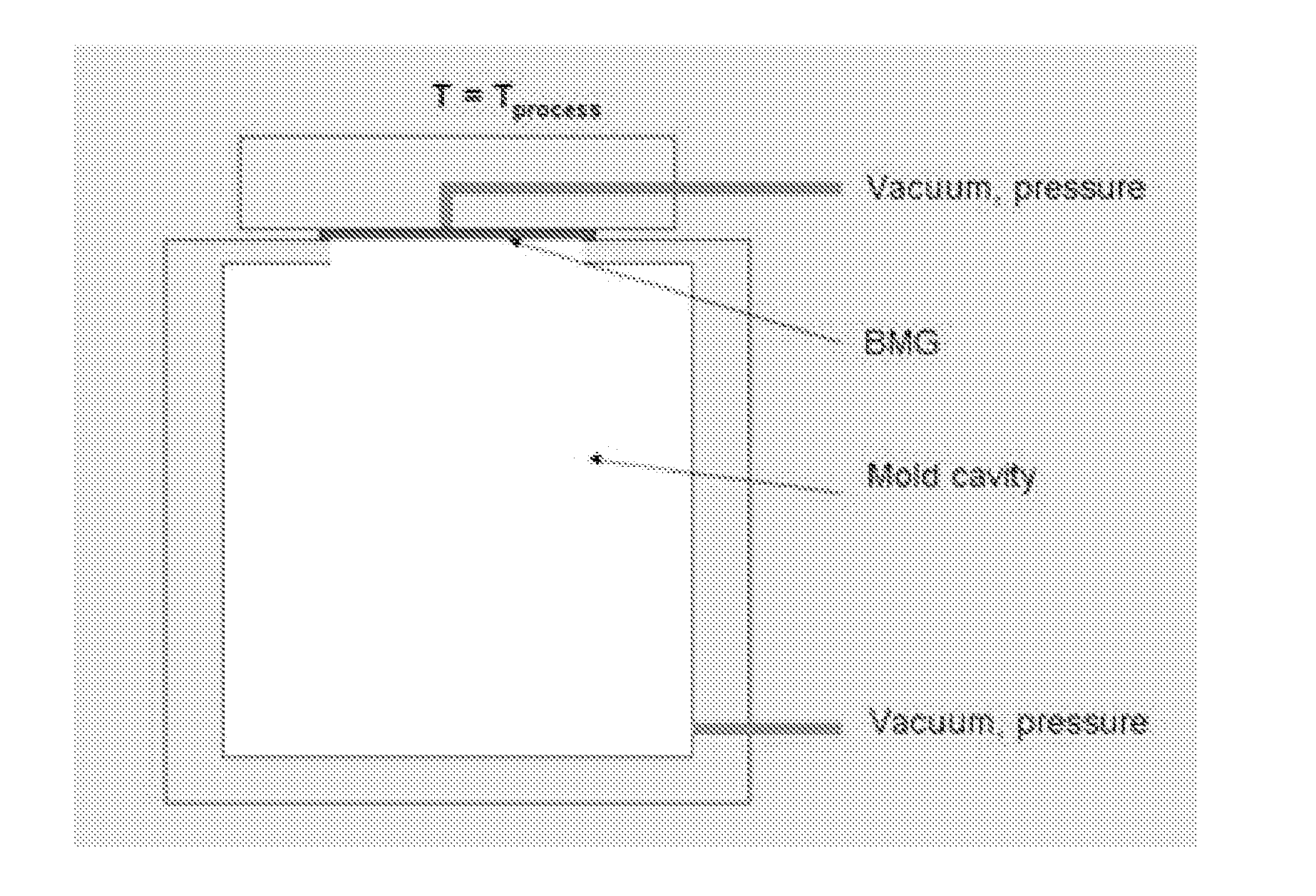
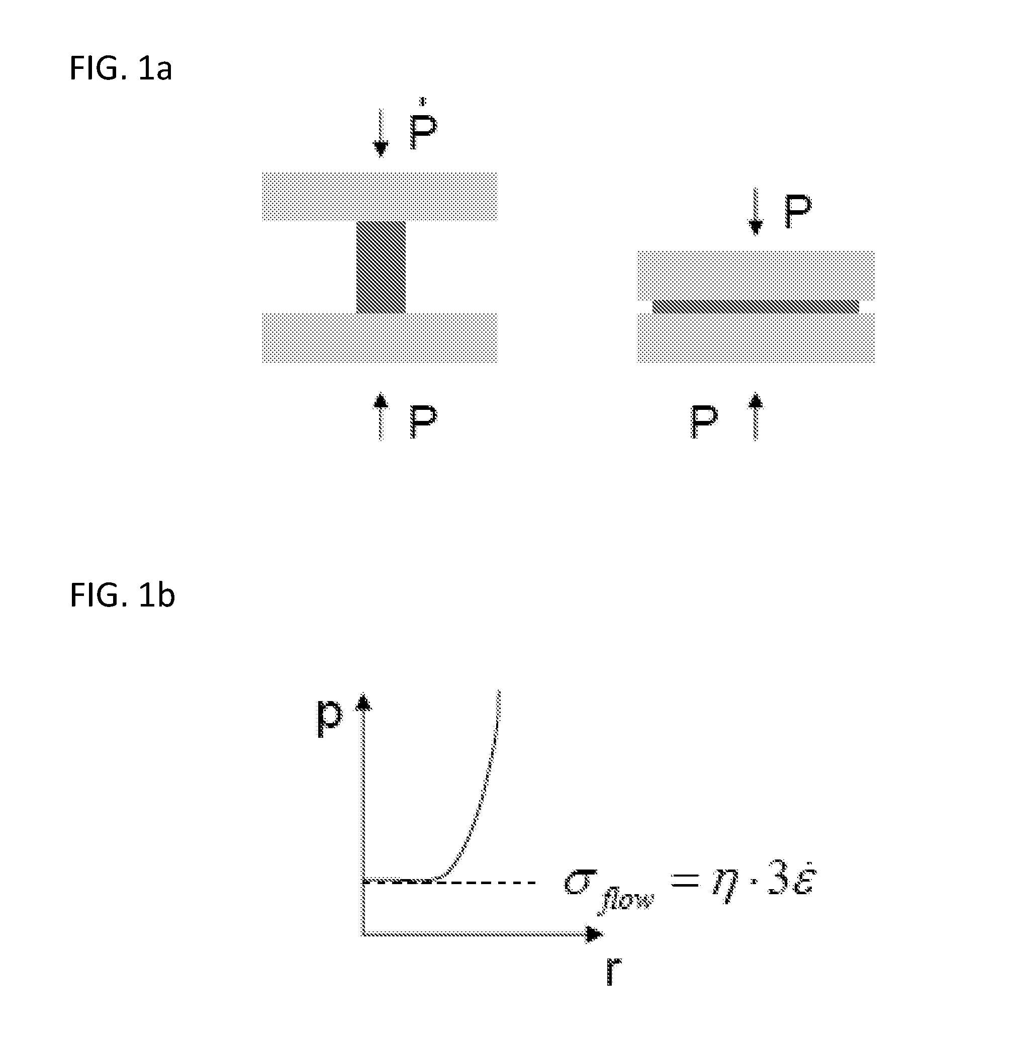
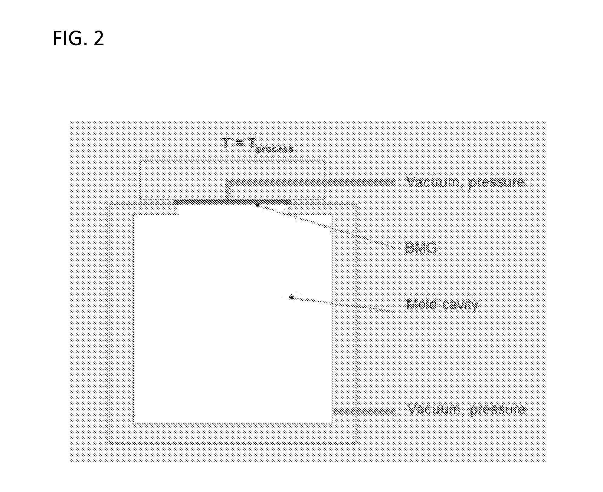
The present invention provides a new way to shape metal materials called bulk metallic glasses (BMG) which allows for better control over their structure without experiencing the common problems associated with traditional methods like sticking and bending. This approach involves expanding a small amount of the raw material through use of high-pressure gases before it comes into direct contact with the surfaces of the tool used for shaping. By doing so, most of the necessary work can be done while keeping the material away from the actual cutting edge, resulting in improved quality and efficiency during production.

Problems solved by technology

The technical problem addressed in this patent text relates to improving the process of shaping articles made from bulk metal glasses (BMGs) through the development of a new and better methodology. Current methods often involve making direct contact between the BMG and the shaping apparatus, limiting its flexibility and causing difficulties in achieving desired forms without compromising on surface quality. The new approach should provide greater freedom to fully exploit the formation capabilities of BMGs while avoiding issues associated with conventional methods.

Method used


Image

  • Method of blow molding a bulk metallic glass
  • Method of blow molding a bulk metallic glass
  • Method of blow molding a bulk metallic glass

Examples


example 1

Forming Pressure Study

[0086]The forming pressures required in the blow molding of a BMG in its supercooled liquid region in accordance with the current invention is demonstrated in FIG. 19. In this study, a 0.8 mm thick Zr44Ti11Cu10Ni10Be25 disk was formed through a circular opening of 4 cm at a temperature of 460° C. The disk section covering the opening was formed into a hemisphere under a pressure, which was generated with the sole power of the human lung (˜104 Pa). The forming process took less than 100 s, which corresponds to a strain rate of ≧10−2 s−1. At the 460° C. processing temperature used in this study, crystallization becomes detectable after 255 s compared with the processing time of 100 s. (See, T. Waniuk, J. Schroers, W. L. Johnson, Physical Review B, 67 (2003) 184203, the disclosure of which is incorporated herein by reference.) The cross-sectional area revealed some thinning of the material. For example, at the edge of the opening the material is 0.72 mm thick comp...

example 2

Mold Forming Study

[0088]FIG. 20 depicts two net-shaped parts that were processed by heating a blank of Zr44Ti11Cu10Ni10Be25 to 460° C. and applying a pressure gradient of 2×10⁵ Pa (0.2 MPa) for ˜40 s. As shown, this study demonstrates that complicated geometries net-shape parts can be replicated with this technique.

example 3

Replication of Surface Features

[0089]FIG. 21 demonstrates both that small features can be replicated using the gas pressure shaping technique of the current invention and that plaster molds may be used. Specifically, in this example a blank of BMG was expanded into a plaster mold. The top image shows the front of the final article formed in accordance with this method, and the bottom image back of the final article formed in accordance with this method. As shown, the smallest features in the mold can be replicated over a large area with this technique even with such low forming pressures.


PUM

PropertyMeasurementUnit
Fractionaaaaaaaaaa
Fractionaaaaaaaaaa
Fractionaaaaaaaaaa

Abstract

A very low pressure gas or blow forming process for shaping a bulk metallic glass (BMG) in its supercooled liquid state that avoids the fractional stick forces experienced by conventional shaping techniques by engineering the expansion of a pre-shape or parison of BMG material such that substantially all of the lateral strain required to form the final article is accomplished prior to the outer surface of the parison contacting the surface of the shaping apparatus is provided. The capability offered by the inventive shaping process to avoid the frictional forces exerted by the shaping apparatus surface allows for the formation of precision net-shape complex multi-scale parts and components using processing conditions inaccessible by conventional processes.

Description


Claims


Application Information

Patent Timeline
Owner YALE UNIV
Why Eureka
Try Eureka