Vehicle suspension arm
- Summary
- Abstract
- Description
- Claims
- Application Information
AI Technical Summary
Benefits of technology
Problems solved by technology
Method used
Image
Examples
first embodiment
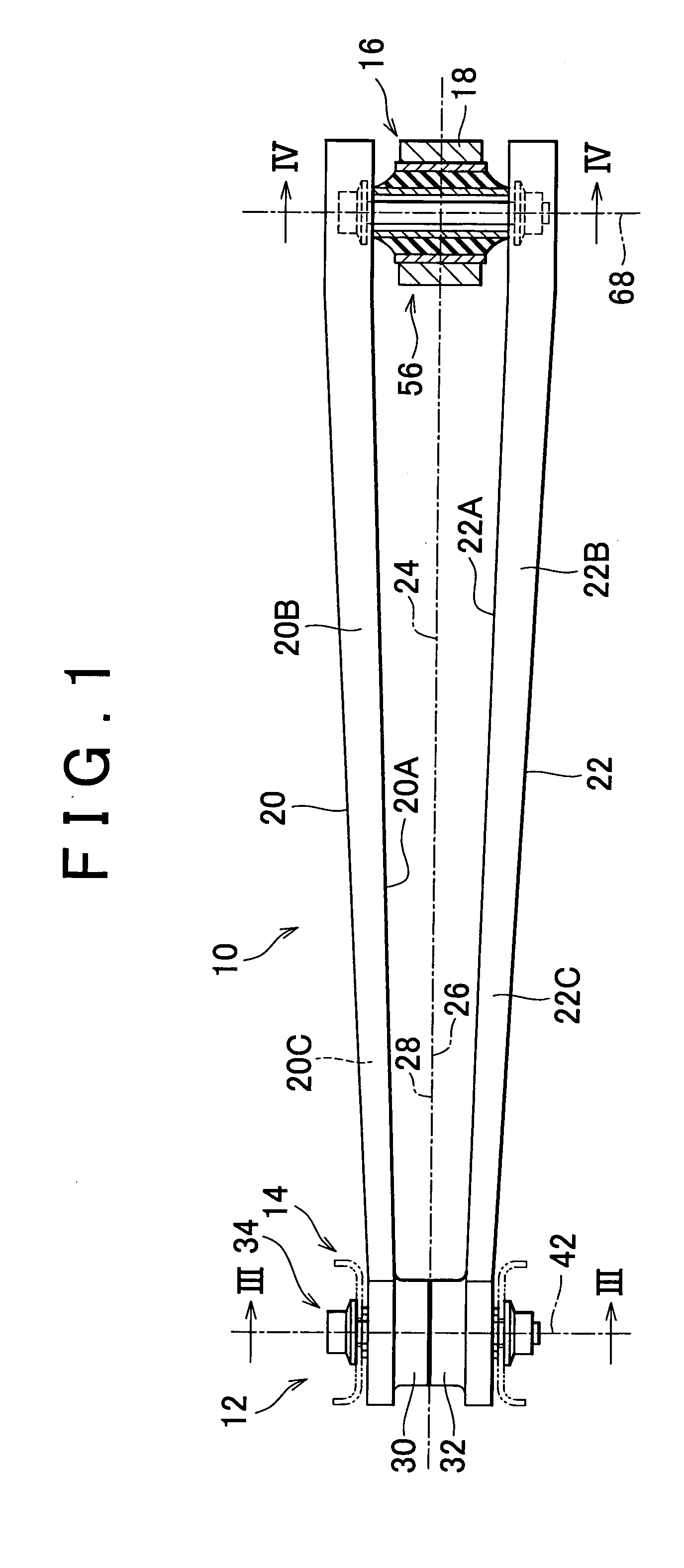
[0076]Especially in the invention illustrated in the drawings, the main body portions 20A and 22A of the arm members 20 and 22 are parallel to each other at one end and the other end. However, the distance between the main body portions 20A and 22A gradually increases in the direction from one end toward the other end in a region between one end and the other end. Further, the width of the flange portions 20B, 20C, 22B, and 22C is constant at one end and the other end, but gradually increases in the direction from one end toward the other end in the region between one end and the other end.
[0077]Owing to the aforementioned construction, although the distance between the arm members 20 and 22 and the cross-sectional areas thereof are not constant along the entire length thereof, shear centers of the arm members 20 and 22 are located on the centerline 24 along the entire length of each arm member 20 and 22. Accordingly, lines 26 and 28, which connect the shear centers of the arm membe...
second embodiment
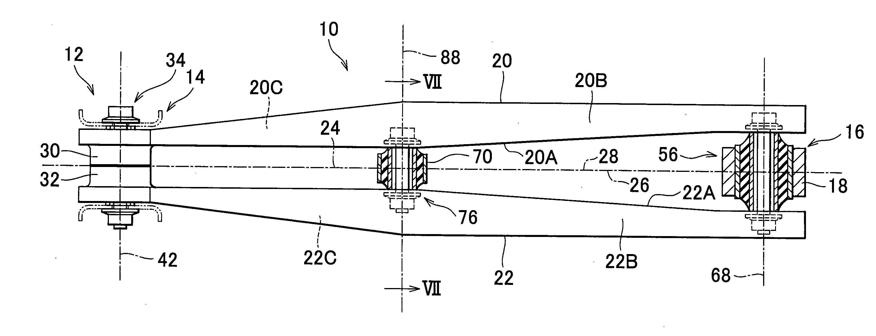
[0085]In the invention, as shown in FIG. 6, the width of the main body portions 20A and 22A of the arm members 20 and 22 is not constant. The width reaches a maximum at a central portion of the suspension arm 10 (in a region to which a stabilizer link 70 is coupled), and gradually decreases in a direction from the central portion toward one end or the other end.
[0086]In a region from one end to the central portion, the main body portions 20A and 22A of the arm members 20 and 22 are parallel to each other, and the distance therebetween is constant. However, in a region between the central portion and the other end, the gap between the main body portions 20A and 22A gradually increases in a direction from the central portion toward the other end. Further, the width of the flange portions 20B, 20C, 22B, and 22C gradually increases in the direction from one end toward the central portion in the region between one end and the central portion, and conversely, gradually decreases in the di...
third embodiment
[0092]FIG. 8 is a perspective view showing in a simplified manner a vehicle suspension arm according to the invention. In FIG. 8, members identical to those shown in FIGS. 1 to 7 are denoted by the same reference symbols as in FIGS. 1 to 7 respectively.
[0093]In this third embodiment of the invention, except the cylindrical portions for receiving the rubber bush device 34 at one end (which correspond to the cylindrical portions 30 and 32 in the first embodiment of the invention and the second embodiment of the invention), the arm members 20 and 22 have constant cross-sectional shapes which are identical to each other along the entire length thereof and in which both ends thereof protrude in the same direction. The arm members 20 and 22 are separated from each other and disposed parallel to each other along the entire length of the arm members 20, 22 on both the sides of the centerline 24, and the lines 26 and 28 connecting the shear centers of the arm members 20 and 22 match the cent...
PUM
 Abstract
Description
Claims
Application Information
 - R&D
- Intellectual Property
- Life Sciences
- Materials
- Tech Scout
- Unparalleled Data Quality
- Higher Quality Content
- 60% Fewer Hallucinations
Browse by: Latest US Patents, China's latest patents, Technical Efficacy Thesaurus, Application Domain, Technology Topic, Popular Technical Reports.
© 2025 PatSnap. All rights reserved.Legal|Privacy policy|Modern Slavery Act Transparency Statement|Sitemap|About US| Contact US: help@patsnap.com


