Circulating structure for drawing-blowing forming machine

A cycle structure and molding machine technology, applied in the field of conveying devices, can solve the problems of limited preforms and low operation efficiency.

Inactive Publication Date: 2009-08-05
CHUM POWER MASCH CORP
View PDF2 Cites 0 Cited by
  • Summary
  • Abstract
  • Description
  • Claims
  • Application Information

AI Technical Summary

Problems solved by technology

[0007] 3. Since the preform seats are separated by a long distance, the preforms passing through the heating device per unit time are limited, resulting in low operating efficiency

Method used


Image

  • Circulating structure for drawing-blowing forming machine
  • Circulating structure for drawing-blowing forming machine
  • Circulating structure for drawing-blowing forming machine

Examples


Embodiment Construction

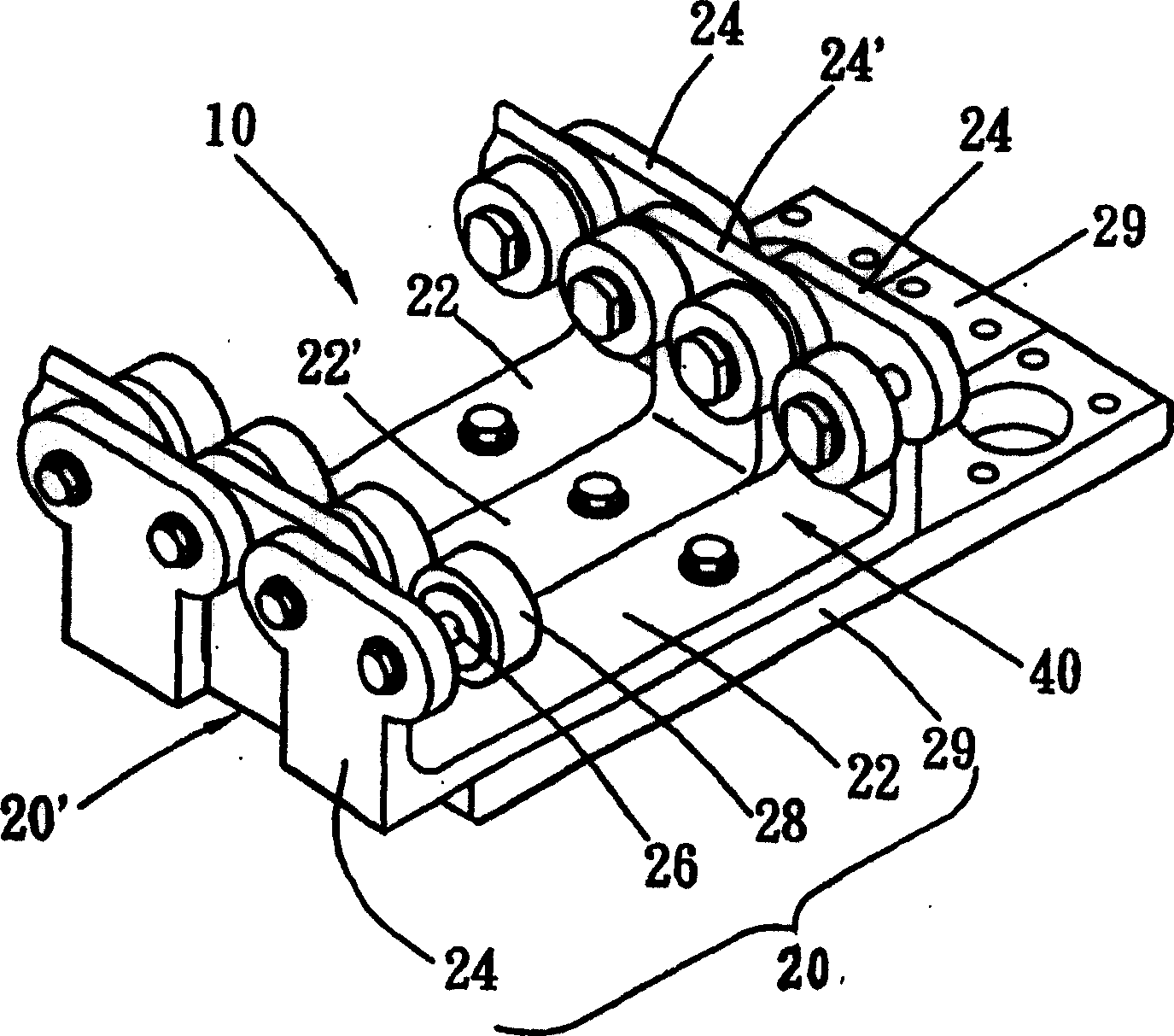
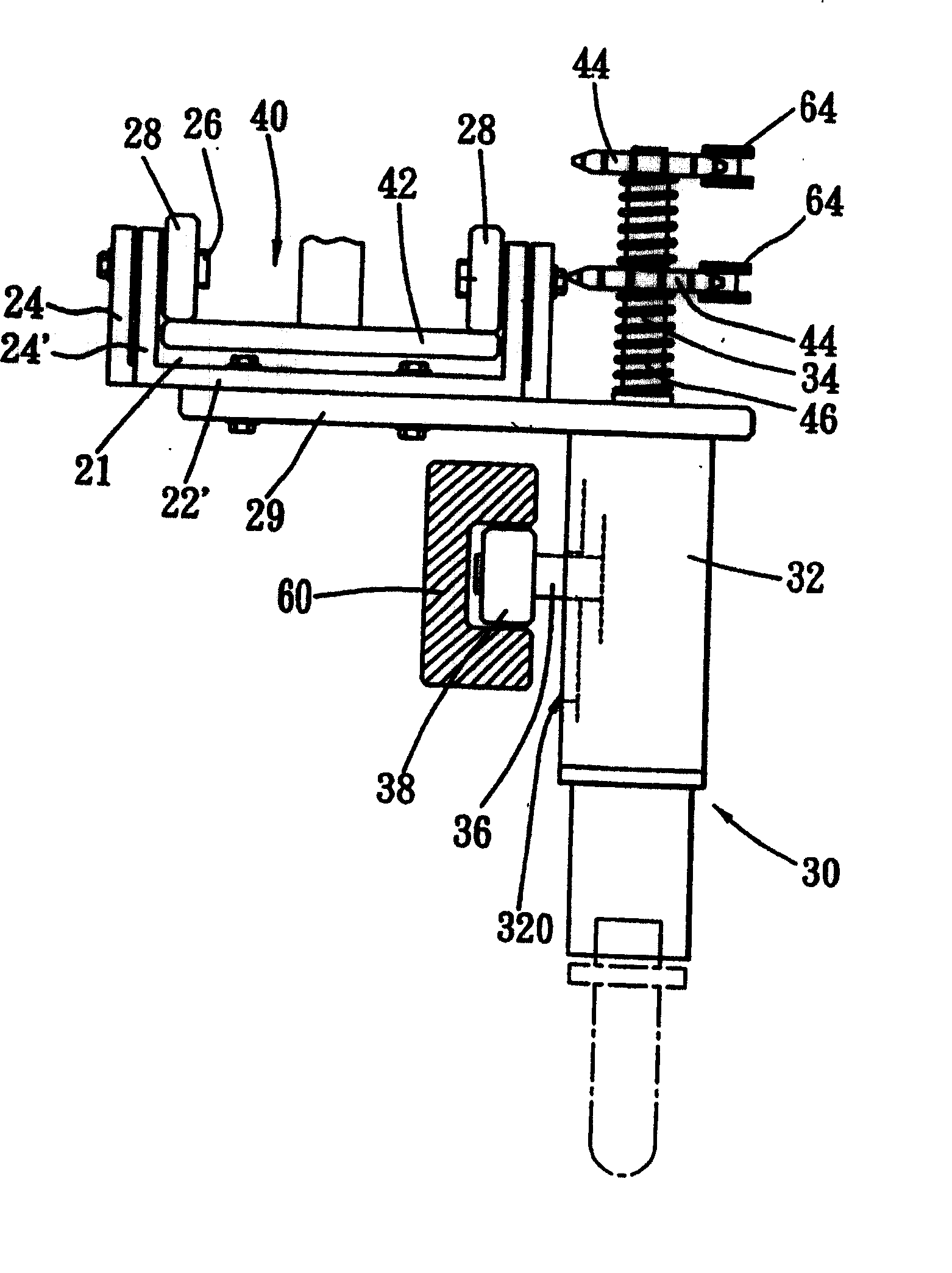
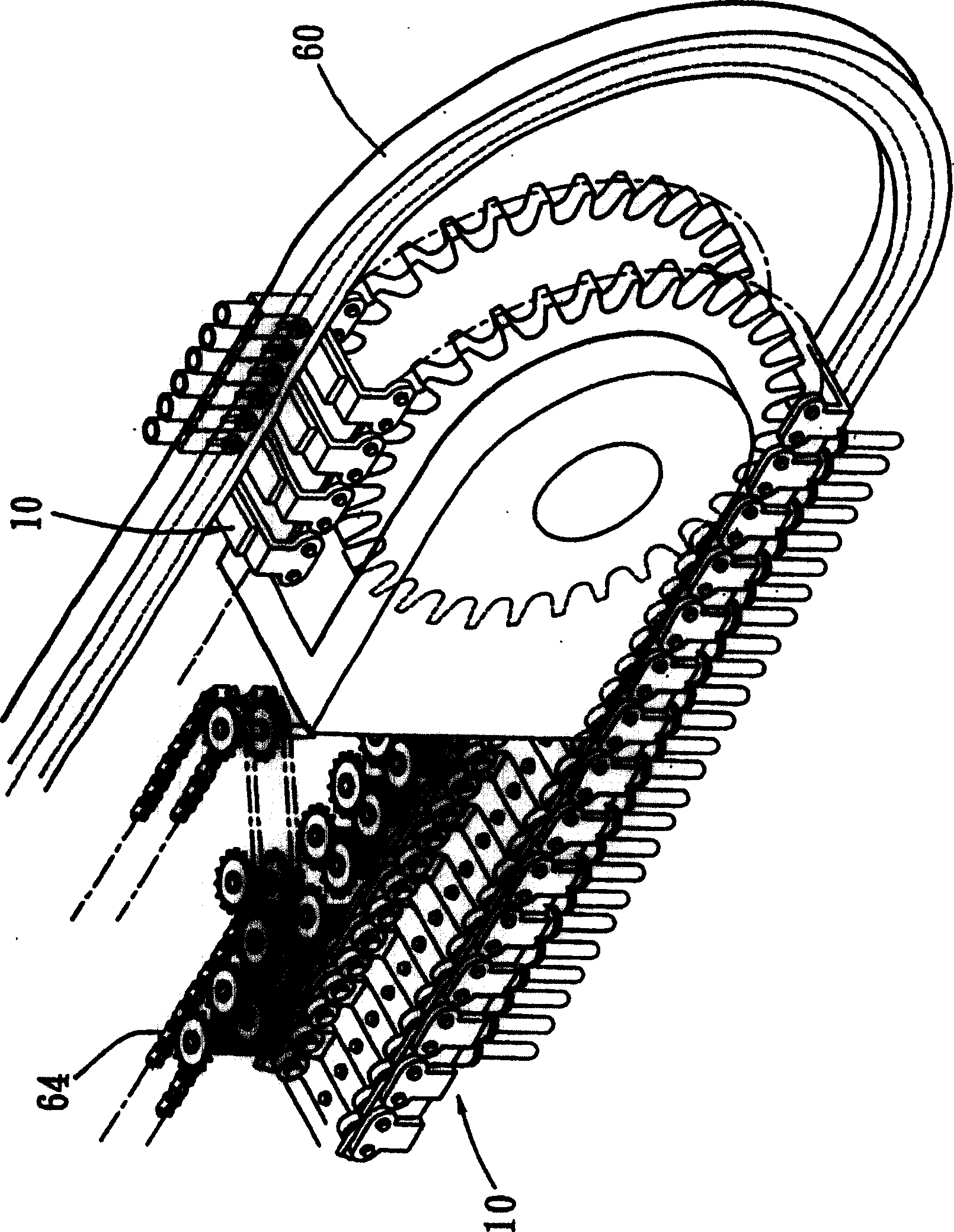
[0019] See also Figure 1 to Figure 5 The circulation structure of the stretch blow molding machine disclosed in the present invention is mainly composed of a conveyor belt 10 that can circulately advance along a predetermined conveying path and one or more preform seats 30 provided on the conveyor belt 10.

[0020] The conveyor belt 10 is formed by pivotally connecting more than one pair of adjacent first chain links 20 and second chain links 20'.

[0021] Each first link 20 has: a bridging portion 22 having a certain length, and its long axis direction is perpendicular to the extending direction of the conveying path, a pair of connecting portions 24 are slightly T-shaped, and respectively protruding on the bridging portion 22 The two ends of each bridge portion 22 (22') and the connecting portion 24 (24') jointly enclose a containing space 40.

[0022] The shape of each second link 20' is almost the same as that of the first link 20, except that the length of the bridge portion ...


PUM


Abstract

The invention provides a circulation structure for a stretch-blow molding machine, comprising a conveyer belt which cycles along a preset route. The conveyer belt consists of two or more chain links which are pivoted one by one in order and a chain link comprises a bridging part with preset length, whose prolate axis is perpendicular to the circulation direction, a pair of connecting parts convexly arranged parallel on the preset places of the bridging part respectively with a preset distance; the connecting parts have preset length and the front ends and the rear ends of the connecting parts are respectively pivoted with the rear ends and the front ends of the adjacent chain links through the same bolt; a accommodation room is confined among the bridging part, a pair of connecting parts and a pair of bolts. A bracket is arranged inside the accommodation room to hold the conveyer belt which has certain length and weight.

Description

【Technical Field】 [0001] The present invention is to provide a conveying device of a stretch blow molding machine, in particular to a circulation structure of a stretch blow molding machine for conveying preforms. 【Background technique】 [0002] In the technical field of stretch blow molding machines, traditional stretch blow molding machines, such as those disclosed in U.S. Patent No. 4,328,760, Chinese Patent No. 9322666.0, and Taiwan Publication No. 378178, are all made up of one or A plurality of conveyor belts circulate forward along a predetermined path. A number of chain links are arranged on the conveyor belt, and a preform seat for carrying the preforms is arranged at a position with a proper interval of chain links, and each preform is passed through a heating unit in turn. The device works with a stretch blow molding device. [0003] The above-mentioned conveyor belt structure is as large as the chain used in general bicycles or transmission mechanisms. Each chain link...

Claims


Application Information

Patent Timeline
Patent Type & Authority Patents(China)
IPC IPC(8): B29C49/42
Inventor 张晋阁
Owner CHUM POWER MASCH CORP
Why Eureka
Try Eureka