Method and apparatus for providing heat to insufflation gases

a gaseous material and gas technology, applied in the field of method and apparatus for heating gaseous material flowing through an insufflator device, can solve the problems of reducing patient recovery time, reducing post-operative care required, and patient trauma

Inactive Publication Date: 2011-04-07
STRYKER CORP
View PDF14 Cites 8 Cited by
  • Summary
  • Abstract
  • Description
  • Claims
  • Application Information

AI Technical Summary

Problems solved by technology

Such surgery, as compared to conventional surgery, reduces patient trauma, decreases patient recovery time, and reduces the amount of post-operative care required.
Heating of the gas in an insufflation device can be quite difficult.
However, the addition of the electrical coiled wire to the tube set raises the cost of the tube set substantially.

Method used


Image

  • Method and apparatus for providing heat to insufflation gases
  • Method and apparatus for providing heat to insufflation gases
  • Method and apparatus for providing heat to insufflation gases

Examples


Embodiment Construction

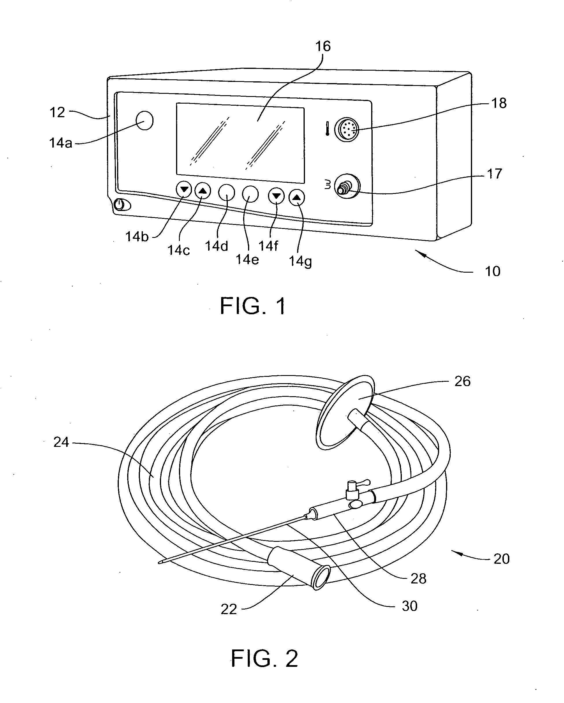
[0026]FIG. 1 shows an insufflator unit 10 including a housing 12 with a plurality of input elements 14a-14g and a display 16. The insufflator unit 10 includes an outwardly projecting flow output port 17 and a temperature connector 18.

[0027]FIG. 2 illustrates an insufflation tube set 20 that includes an input connector 22 at a proximate end for connection of the tube set 20 to the flow output port 17 of the insufflator unit 10. The input connector 22 attaches at its other end to tubing 24. The tubing 24 of the tube set 20 includes a filter 26 provided thereon for filtering any backflow of gas or fluid. The distal end of the tubing 24 has a trocar 28 mounted thereto. The trocar 28 includes a needle-type element 30 for insertion into the abdominal cavity of a patient to perform a surgical procedure. A small incision is made in the body of a patient, and one end of the trocar 28 is inserted into the abdominal cavity.

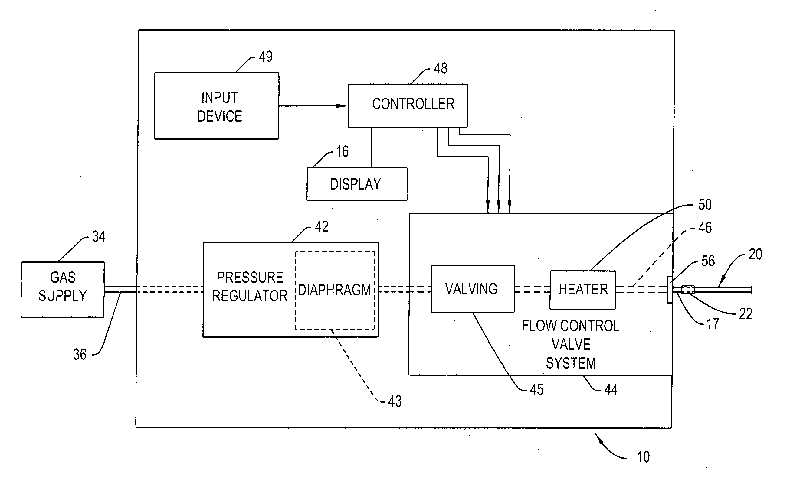
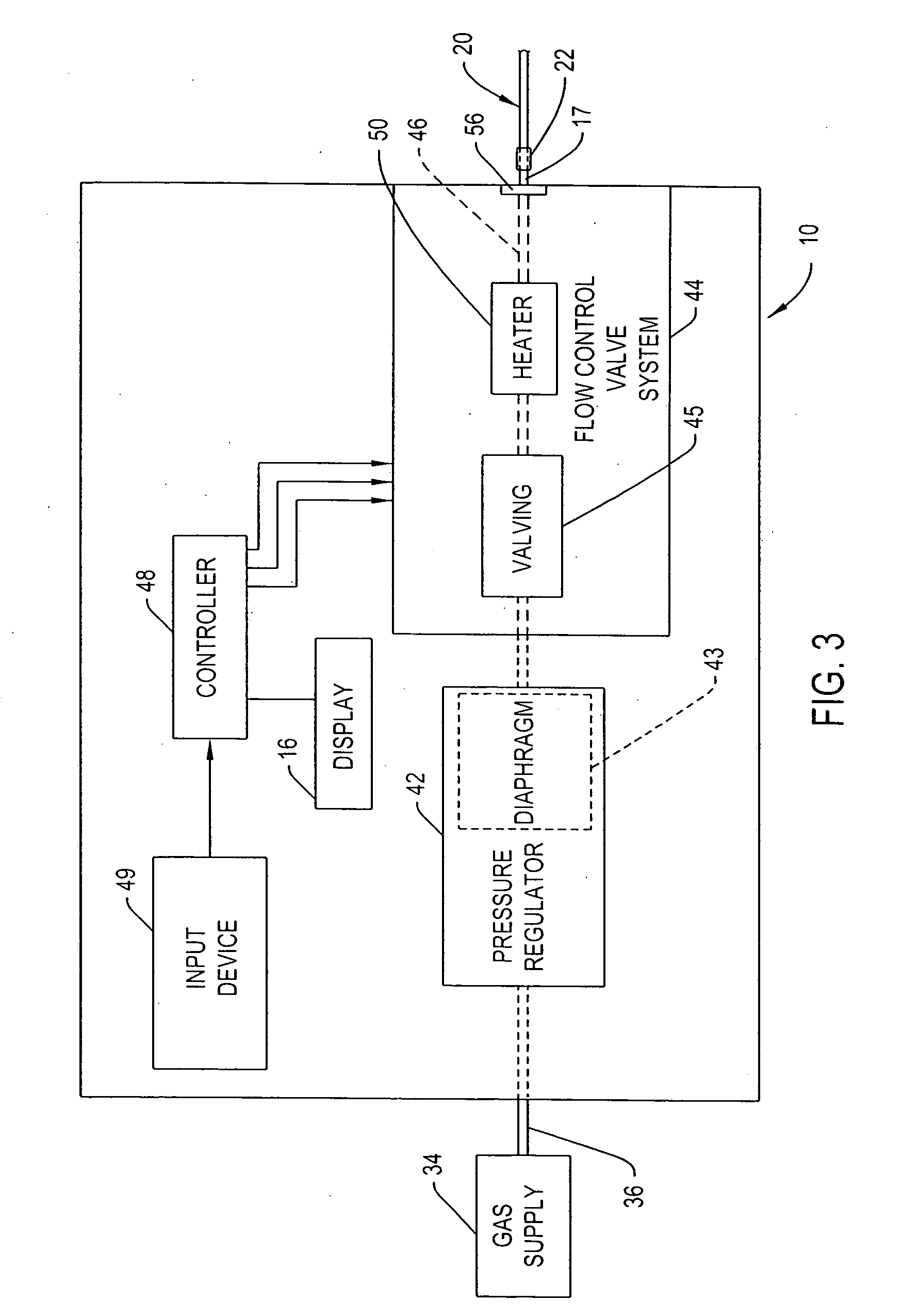
[0028]As illustrated in FIG. 3, a gas supply 34 connects to the insuffl...


PUM


Abstract

An insufflator device is provided that connects to a disposable tube set for providing gas to fill an abdominal cavity of a patient to enable surgical procedures. The insufflator tube set includes a warming sheath, a double lumen design, or a heating strip for providing warmth to the insufflation gas being conveyed through the tube set. A method of heating insufflation gases is also provided.

Description

CROSS REFERENCE TO RELATED APPLICATION[0001]This application claims the benefit of U.S. Provisional Application No. 61 / 278,278, filed Oct. 5, 2009, the disclosure of which is hereby incorporated by reference in its entirety.FIELD OF THE INVENTION[0002]This invention is generally directed to a method and apparatus for warming gaseous material flowing through an insufflator device.BACKGROUND OF THE INVENTION[0003]Surgeons have used laparoscopic surgery to perform a variety of procedures. Such surgery, as compared to conventional surgery, reduces patient trauma, decreases patient recovery time, and reduces the amount of post-operative care required.[0004]To perform a laparoscopic operation, a sufficient area for the introduction of a laparoscope and other instruments must be provided by raising the abdominal wall and separating the abdominal wall from the organs enclosed in the peritoneal cavity, commonly referred to as the abdominal cavity. Separation is typically obtained by pressuri...

Claims


Application Information

Patent Timeline
Patent Type & Authority Applications(United States)
IPC IPC(8): A61M31/00
CPCA61B17/3474A61M13/003A61M2205/364A61M5/44A61M2205/8206A61M16/1095A61M2205/3653
Inventor IRANITALAB, PAJHANDXIANG, XIAODONG
Owner STRYKER CORP
Why Eureka
Try Eureka