System with brake to limit manual movement of member and control system for same

Active Publication Date: 2011-04-07
MAKO SURGICAL CORP
View PDF32 Cites 79 Cited by
  • Summary
  • Abstract
  • Description
  • Claims
  • Application Information

AI Technical Summary

Benefits of technology

[0011]According to yet another aspect, a control system is configured to be integrated with a robotic system having a moveable member. The control system includes a controller programmed to determine whether at least a portion of the moveable member of the robotic system is in a defined braking region, generate a signal configured to cause a defined braking force to be applied to inhibit

Problems solved by technology

The above-described interactive robotic system, though useful for knee replacement surgery, it is not optimally suited for types of surgery, such as hip replacement surgery, that require the use of multiple surgical tools having different functions (e.g., reaming, impacting), different configurations (e.g., straight, offset), and different weights.
A system designed to accommodate a variety of tools may be prohibitively complex and require multiple end effectors, and removing and attaching different types of tools to the robotic arm during a surgical procedure could increase the time to perform the procedure.
Angular orientation of both the reamed socket and the implanted acetabul

Method used


Image

  • System with brake to limit manual movement of member and control system for same
  • System with brake to limit manual movement of member and control system for same
  • System with brake to limit manual movement of member and control system for same

Examples


Embodiment Construction

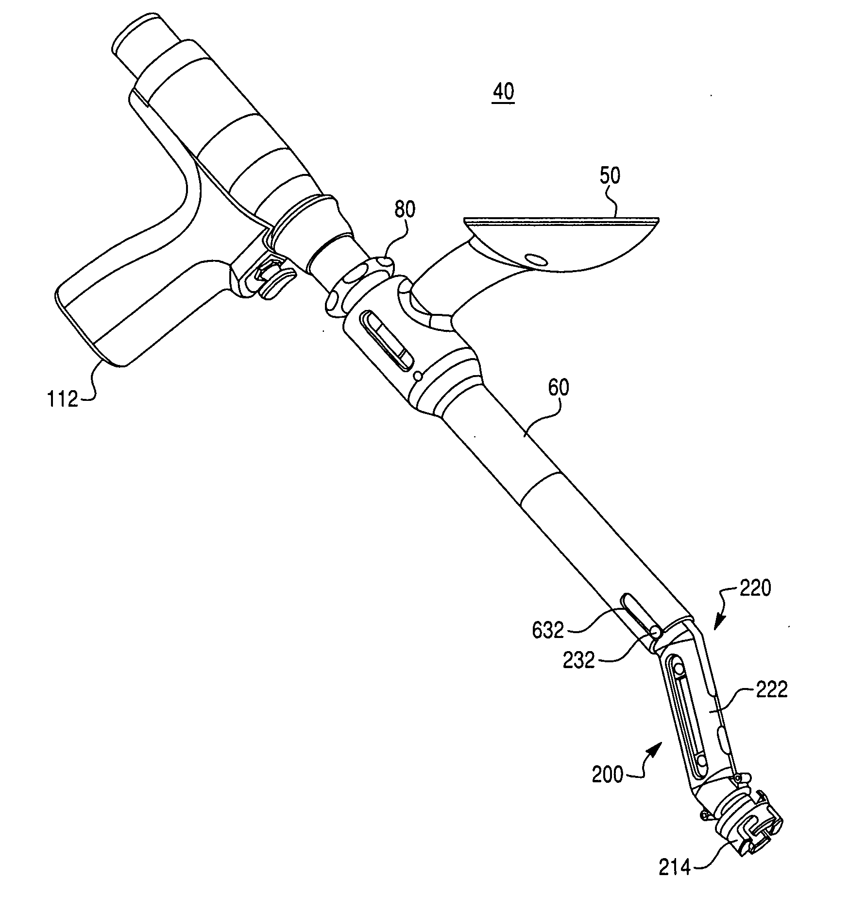
[0049]Presently preferred embodiments of the invention are illustrated in the drawings. An effort has been made to use the same or like reference numbers throughout the drawings to refer to the same or like parts. Although this specification refers primarily to a robotic arm for orthopedic hip replacement, it should be understood that the subject matter described herein is applicable to other types of robotic systems, including those used for surgical and non-surgical applications, as well as to other joints of the body, such as, for example, a shoulder joint.

Overview

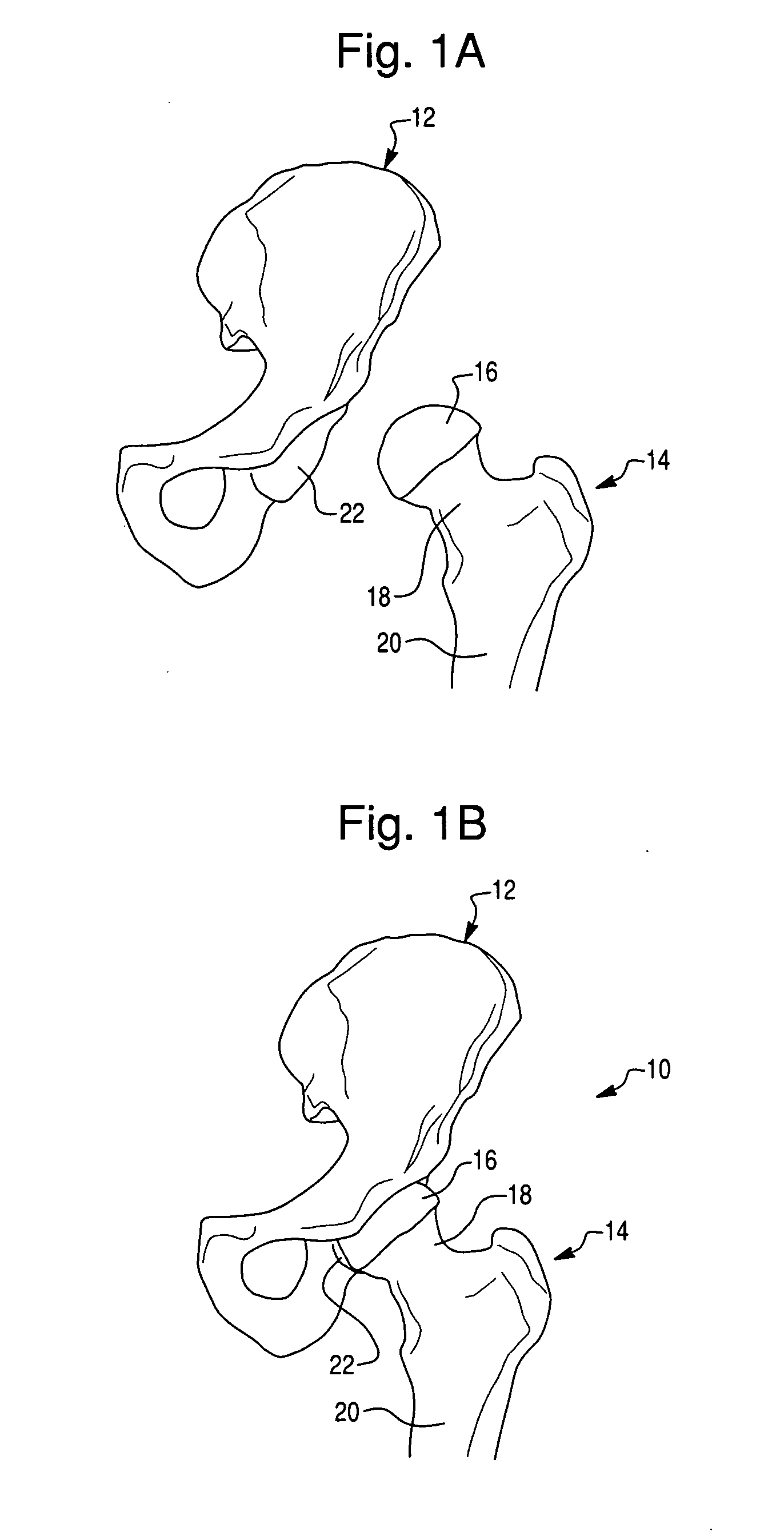
[0050]The hip joint is the joint between the femur and the pelvis and primarily functions to support the weight of the body in static (for example, standing) and dynamic (for example, walking) postures. FIG. 1A illustrates the bones of a hip joint 10, which include a pelvis 12 (shown in part) and a proximal end of a femur 14. The proximal end of the femur 14 includes a femoral head 16 disposed on a femoral neck 18. The ...


PUM


Abstract

A system includes a moveable member configured to permit a user to manually move at least a portion of the moveable member to permit an object coupled to the moveable member to be manipulated in space and thereby facilitate the performance of a task using the coupled object. The moveable member is configured to couple to at least a first object and a second object that is interchangeable with the first object and has a substantially different weight than the first object. A brake is configured to limit manual movement of at least the portion of the moveable member to inhibit manipulation in space of the coupled object, both when the moveable member is coupled to the first object and when the moveable member is coupled to the second object.

Description

CROSS-REFERENCE TO RELATED PATENT APPLICATIONS[0001]This application claims priority to U.S. Provisional Patent Application Ser. No. 61 / 278,066, filed Oct. 1, 2009; U.S. Provisional Patent Application Ser. No. 61 / 339,460, filed Mar. 4, 2010; U.S. Provisional Patent Application Ser. No. 61 / 339,756, filed Mar. 9, 2010; and U.S. Provisional Patent Application Ser. No. 61 / 401,209, filed Aug. 9, 2010, each of which is hereby incorporated by reference in its entirety.BACKGROUND OF THE INVENTION[0002]1. Field of Invention[0003]The present invention relates generally to robotic systems and, more particularly, to surgical systems for orthopedic joint replacement surgery.[0004]2. Description of Related Art[0005]Robotic systems are often used in applications that require a high degree of accuracy and / or precision, such as surgical procedures or other complex tasks. Such systems may include various types of robots, such as autonomous, teleoperated, and interactive.[0006]Interactive robotic syst...

Claims


Application Information

Patent Timeline
IPC IPC(8): B25J9/16B25J18/00
CPCA61B17/1617A61B17/162A61B17/1631A61B17/1666Y10T74/20305A61B19/56A61B2017/00477A61F2/34A61F2/36A61B19/2203A61B34/25A61B90/03A61B34/30A61B34/74A61B2090/08021A61B2090/062A61B17/56A61F2/46B25J18/00A61B34/20A61B2034/2051A61B17/1655A61B17/1659A61B17/1664A61B17/1684A61B2017/00199A61F2/4607A61F2/4609
Inventor ZIAEI, KAMMOSES, DENNIS
Owner MAKO SURGICAL CORP
Why Eureka
Try Eureka