
Inkjet print apparatus and inkjet print method

a technology of inkjet printing and inkjet printing, which is applied in the field of inkjet printing method and inkjet printing apparatus, can solve the problems of deteriorating image quality, uneven concentration of mask pattern tracing, and air current turbulen

Inactive Publication Date: 2011-04-14
CANON KK
View PDF3 Cites 2 Cited by
  • Summary
  • Abstract
  • Description
  • Claims
  • Application Information

AI Technical Summary

Benefits of technology

[0009]Hence, the present invention has an objective to provide an inkjet print apparatus and an inkjet print method capable of a print without concentration unevenness.
[0012]According to the inkjet print apparatus of the present invention, each of the different mask patterns includes a first area and a second area, the first area being where the binary image data is thinned out at a relatively high percentage, the second area being where the binary image data is thinned out at a relatively low percentage. A difference in print percentage between the first area and the second area in each of both edge parts of an image to be printed where the print head scans back is smaller than a difference in print percentage between the first area and the second area in a center part of the image. Thereby, an inkjet print apparatus capable of a print without concentration unevenness can be provided.

Problems solved by technology

However, print operations using such high-density, long print head can cause the following problem.
In addition, simultaneous ejection of many ink droplets from the print head having nozzles densely arranged generates turbulence in the air current.
As a result, landing positions of the ink droplets are shifted from their desired positions, drastically deteriorating the image quality.
Thus, concentration unevenness tracing the mask patterns is reflected in the printed image in some cases.

Method used


Image

  • Inkjet print apparatus and inkjet print method
  • Inkjet print apparatus and inkjet print method
  • Inkjet print apparatus and inkjet print method

Examples


first embodiment

(Basic Configuration)

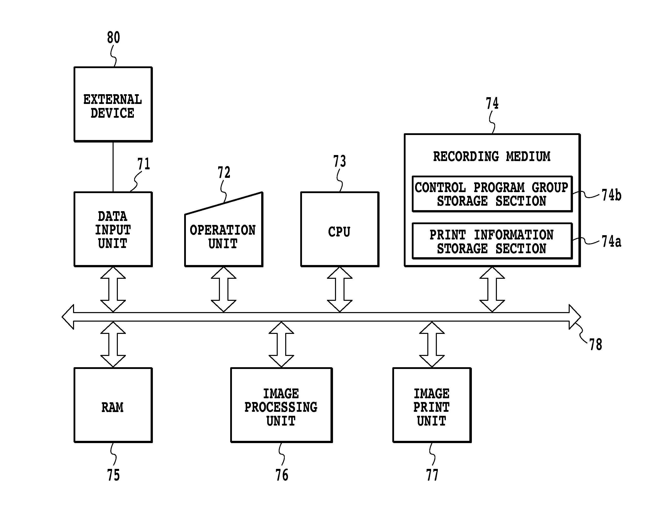
[0020]A basic configuration of a first embodiment of the present invention is described below with reference to the drawings.

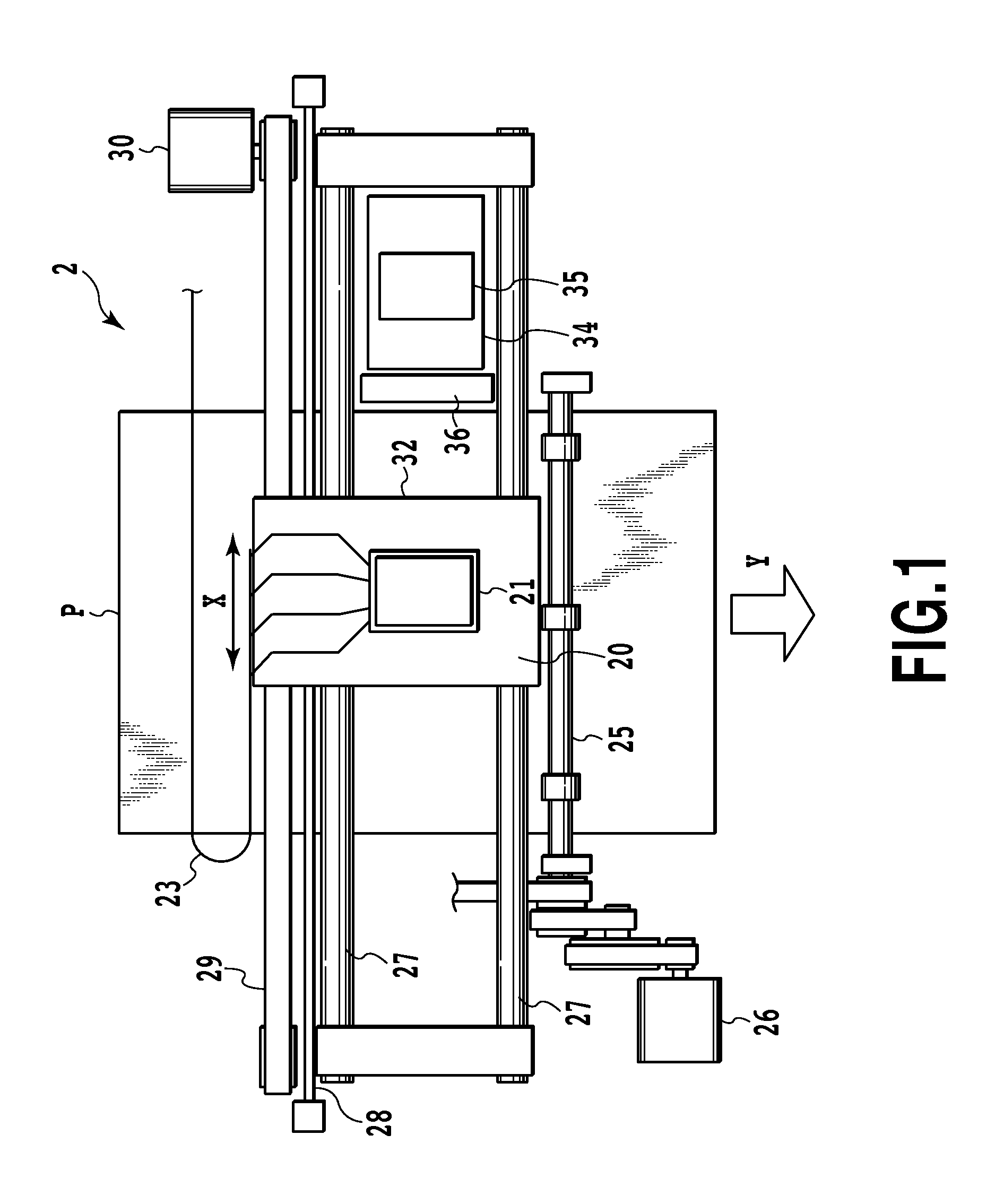
[0021]FIG. 1 is a front view showing a schematic configuration of a serial-type inkjet print apparatus (also simply called a print apparatus below) applicable to the present embodiment. A carriage 32 is supported by a guide shaft 27 and a linear encoder 28 while being allowed to reciprocate along a main scan direction (an X direction). A drive belt 29 moves by being driven by a carriage motor 30 and thus reciprocates the carriage 32 along the guide shaft 27. An inkjet print head 21 (also simply called a print head 21 below) is detachably mounted on the carriage 32.

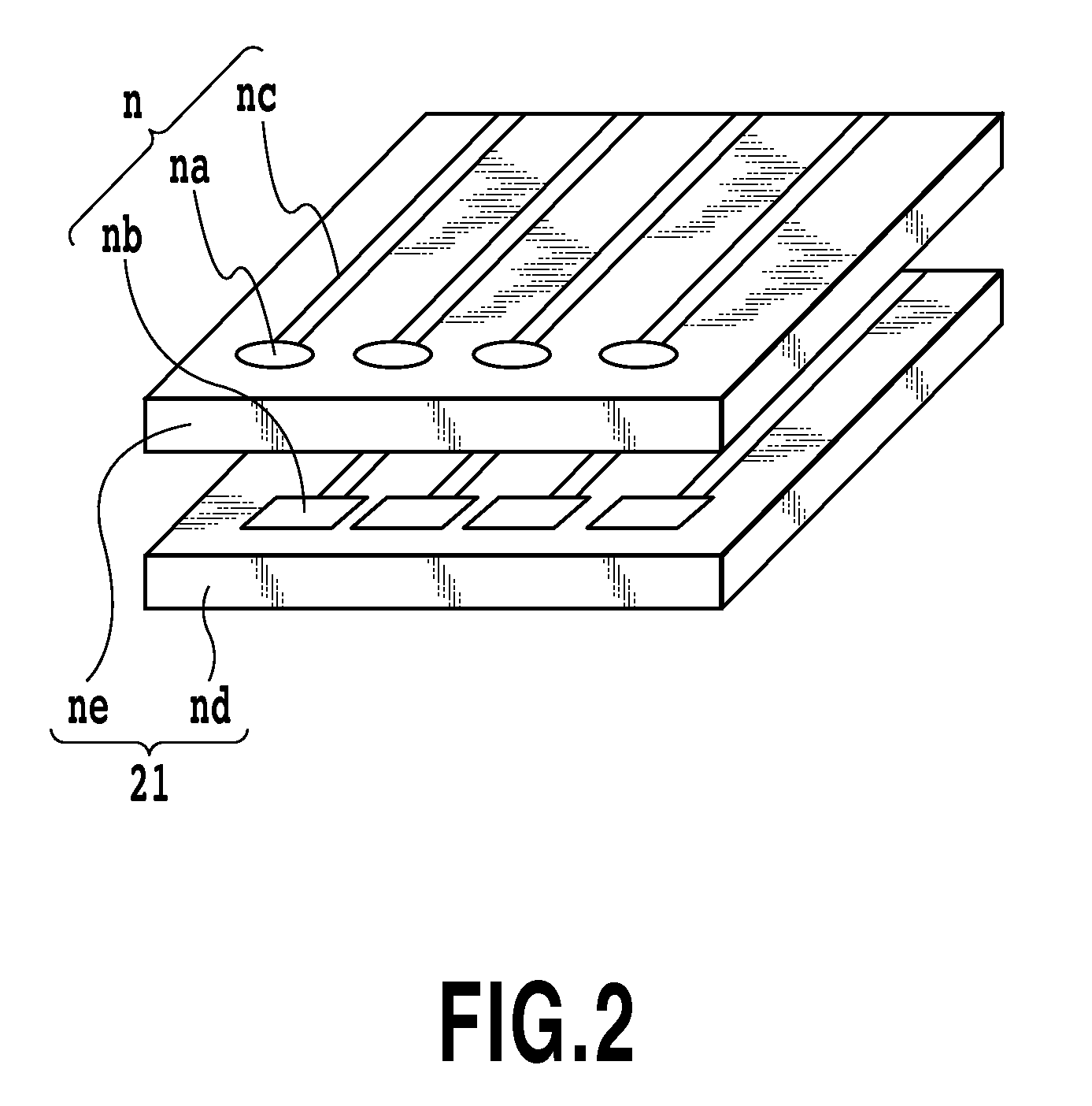
[0022]In the print head 21, multiple ejecting portions (also called nozzles below) for ejecting ink are arranged. A liquid path formed in each nozzle of the print head 21 is provided with a heating element (an electric-heat converter) that generates heat energy for ejecting ink i...

second embodiment

[0047]A second embodiment of the present invention is described below with reference to the drawings. Note that the basic configuration of the present embodiment is the same as that of the first embodiment, and therefore only the characteristic configuration is described below.

[0048]FIG. 6 is a plain view schematically showing a portion of a mask pattern 111. FIG. 6 shows a portion of the mask pattern 111 is an example of a mask used in the so-called two-pass print method in which each print area is completed through two scans compensating for each other. The mask pattern 111 includes, in its center part, high-print-percentage areas Hn each having a print percentage of 50% or higher and low-print-percentage areas Ln each having a print percentage of lower than 50%. FIG. 6 shows a portion of the mask pattern 111 used for an image formed by a first scan, or more specifically, shows only a portion of the mask pattern 111 used for an area from the left edge to almost the center of a pri...


PUM


Abstract

An objective is to provide an inkjet print apparatus and an inkjet print method capable of a print without concentration unevenness. To achieve the objective, in a multiple-pass print using mask patterns each having low-print-percentage areas and high-print-percentage areas, the print-percentage difference between high-print-percentage areas and low-print-percentage areas is cancelled out in left-edge and right-edge parts of an image to be printed.

Description

BACKGROUND OF THE INVENTION[0001]1. Field of the Invention[0002]The present invention relates to an inkjet print method and an inkjet print apparatus by which an image is printed on a print medium by using an inkjet print head having nozzle arrays each including ink-ejecting nozzles densely arranged.[0003]2. Description of the Related Art[0004]With the spread of information processing devices and communication devices, such as computers and word processors, there are more and more demands for output devices that output digital image information processed by such devices. As one of such output devices, an inkjet print apparatus that forms dots on a print medium through ejection of ink droplets is rapidly spreading. Recent demands increasingly call for output devices capable of outputting color print images. Since output of photograph images particularly requires high image quality, reduction in volume of each ink droplet is anticipated.[0005]Meanwhile, with the recent technical devel...

Claims


Application Information

Patent Timeline
IPC IPC(8): B41J29/38
CPCB41J2/2125G06K15/107B41J2/2132
Inventor KYOSHIMA, MASAYUKIOIKAWA, MASAKITOMIZAWA, KEIJI
Owner CANON KK
Learn More