
Relief printing plate and method for producing organic el device using the same

a printing plate and relief technology, applied in the manufacture of electrode systems, cold cathode manufacturing, electric discharge tube/lamp manufacture, etc., can solve the problems of lack of linearity of pattern shape thus formed, difficulty in maintaining pattern accuracy of mask, and difficulty in using patterning or coating colors distinctly. , to achieve the effect of not being uneven

Inactive Publication Date: 2013-07-25
TOPPAN PRINTING CO LTD
View PDF8 Cites 1 Cited by
  • Summary
  • Abstract
  • Description
  • Claims
  • Application Information

AI Technical Summary

Benefits of technology

The invention describes a method for making an organic light source without unevenness. This is achieved by using a printing plate with multiple patterns to create a layer of organic material in a uniform way. This results in an organic electronic device that can produce light without any unevenness.

Problems solved by technology

This method is excellent for forming a uniform thin film but has a problem that the pattern accuracy of the mask is difficult to maintain on forming on a large substrate.
Examples of the wet coating method include a spin coating method, a bar coating method, an extrusion coating method and a dip coating method, but these methods are difficult to use for patterning or coating colors distinctly, and a pattern printing method, such as an ink-jet method and a printing method is necessarily employed for patterning with high definition.
However, ink droplets ejected from the nozzle are in a spherical shape, and thus the ink spreads to a circular shape on impacting on the substrate, which may cause a problem that the pattern shape thus formed lacks linearity, or the pattern lacks linearity due to deteriorated impact accuracy.
The organic EL device or a display often employs a glass substrate as a substrate thereof, for which a method using a hard printing plate, such as a metal printing plate, for example, a gravure printing method, is not suitable.
In the case where the ink thus transferred in the aforementioned printing process is not sufficiently leveled, printing defects may occur, such as a cupping phenomenon, in which the ink is not transferred to the center portion of the printed line, and a marginal phenomenon, in which the ink is not transferred to the outer portion of the printed line.
When the phenomena occur, the organic material layer may have uneven thickness within a pixel, which causes light emission unevenness.

Method used


Image

  • Relief printing plate and method for producing organic el device using the same
  • Relief printing plate and method for producing organic el device using the same
  • Relief printing plate and method for producing organic el device using the same

Examples


example

Example 1

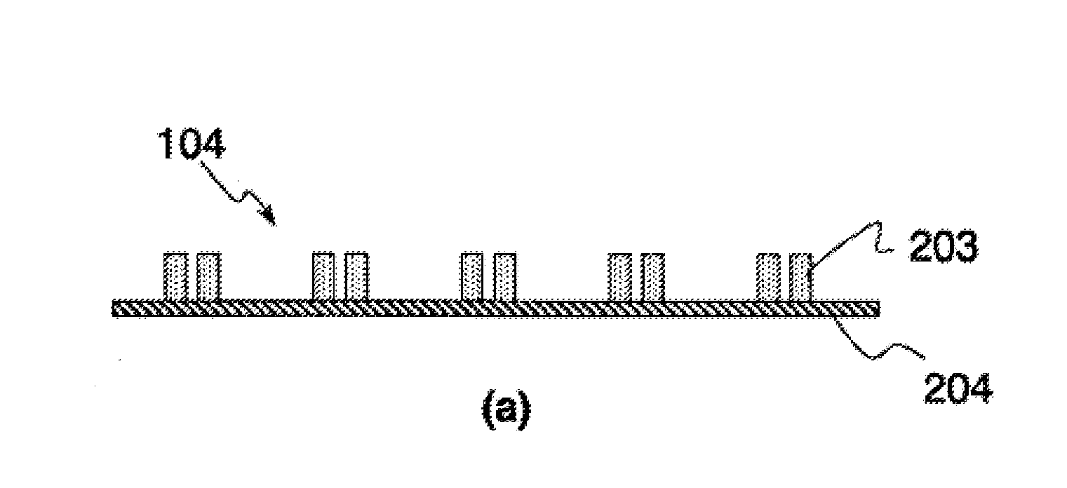
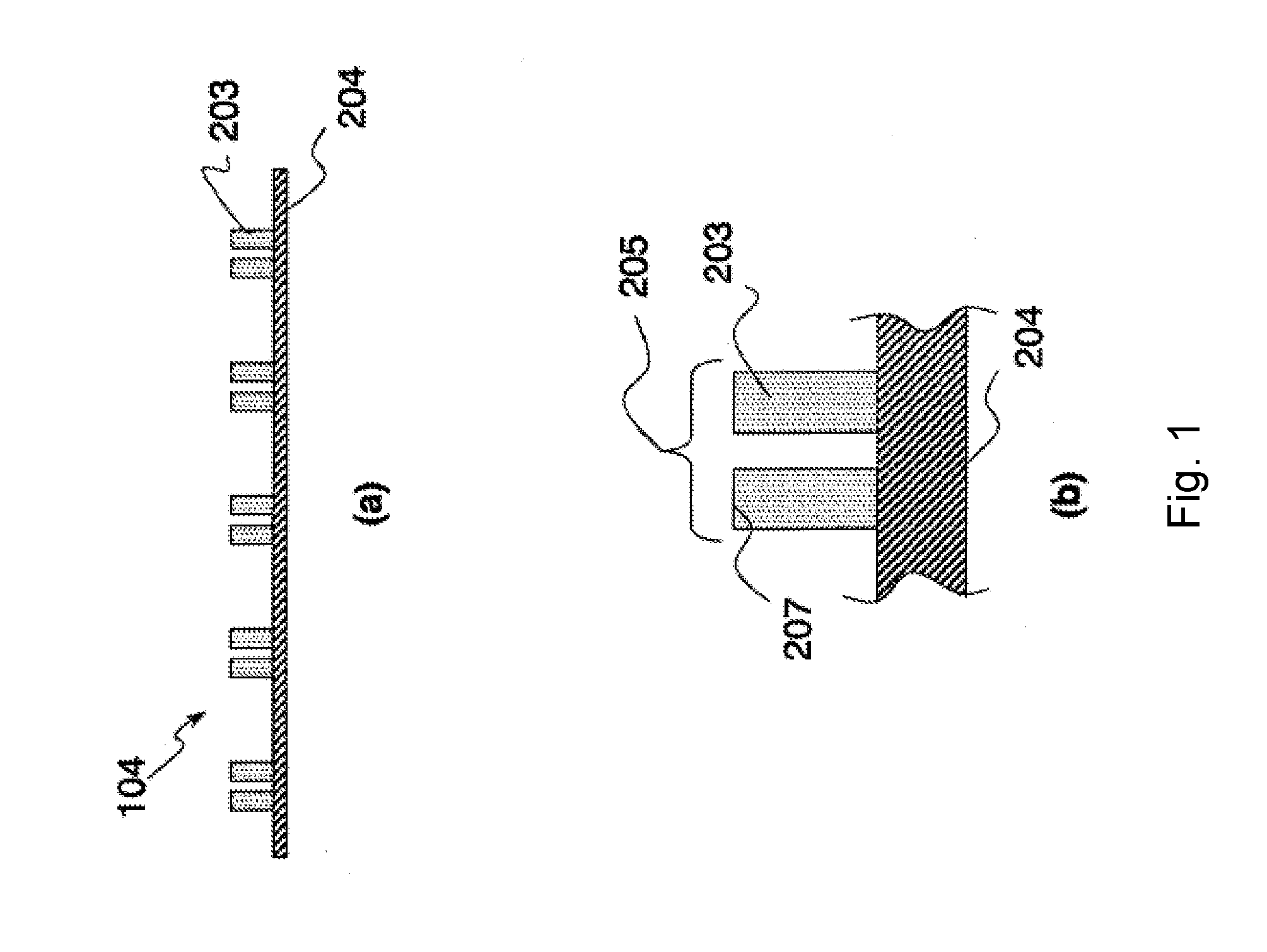
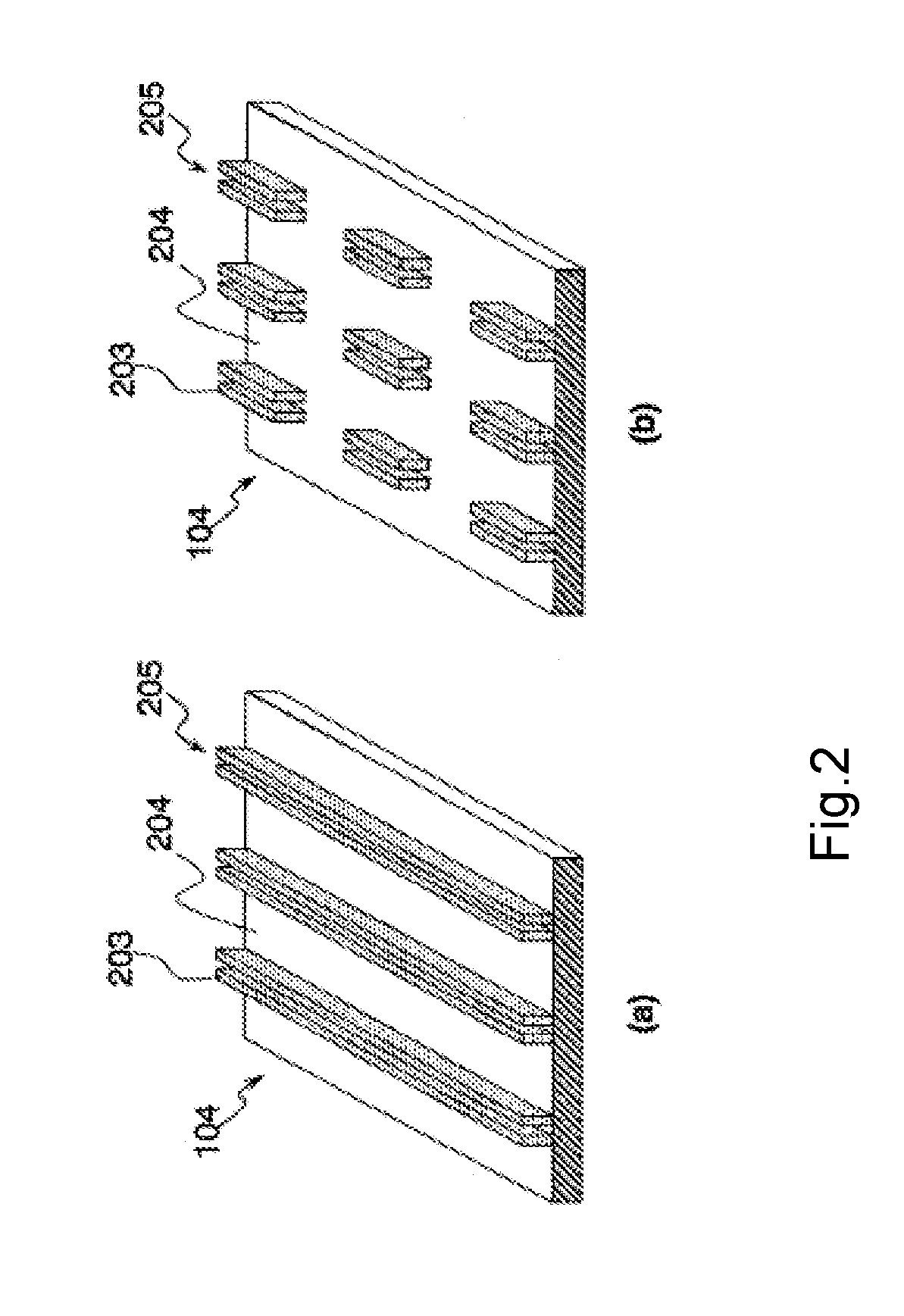
Production of Photosensitive Resin Relief Printing Plate 104

[0115]A 42 nickel material having a thickness of 250 μm was used as a substrate 204, and an acrylic binder resin solution having a black pigment kneaded therein was coated on the substrate 204 to make a dry thickness of 10 μm, followed by drying, thereby forming an antireflection layer.

[0116]A photosensitive resin composition formed by kneading a water soluble polyamide as a major component, dipentaerythritol hexakisacrylate as a radical polymerizable monomer and 2,2-dimethoxy-1,2-diphenylethan-1-one (produced by Ciba Specialty Chemicals Co., Ltd.) as a photopolymerization initiator was melt-coated on the surface of the substrate 204 to make a total thickness of the plate of 310 μm, thereby producing a photosensitive resin layer, on which a polyethylene terephthalate film (thickness: 125 μm, produced by Teij in DuPont Films Japan Ltd.) having a polyvinyl alcohol solution coated thereon to make a dry thickness of 1 ...

example 2

[0124]In Example 2, a device was produced in the same manner as in Example 1 except that the relief pattern 203 thus produced had a width of 25 two relief patterns were formed with a distance of 10 μm to form a relief pattern group 205 having a width of 60 the pixel size was 80 μm×150 μm, the organic light emitting inks used had a viscosity of 120 mPa·s, and 20 substrates were continuously printed in the printing process.


PUM


Abstract

A method is provided for forming a uniform light emitting medium layer by a relief printing method without occurrence of printing defects. The method includes producing an organic EL device containing a substrate having thereon a pixel electrode, pixel regions that are demarcated with a partition wall on the pixel electrode, a light emitting medium layer having a light emitting layer containing at least an organic light emitting material on the pixel regions, and a counter electrode facing the pixel electrode. The method can have a step of forming at least one layer constituting the light emitting medium layer by a relief printing method, and the ink used in the relief printing method being transferred from two or more adjacent relief patterns within one of the pixel regions and being integrated by flow thereof to form the light emitting medium layer.

Description

CROSS-REFERENCE TO RELATED APPLICATION[0001]This application is a continuation of International Application No. PCT / JP2011 / 070132, filed Sep. 5, 2011, which is incorporated herein by reference.BACKGROUND OF THE INVENTION[0002]1. Field of the Invention[0003]The present invention relates to an organic EL device having an organic luminescent layer that is formed by a relief printing method, a method for producing the same, and a relief printing plate used therefor.[0004]2. Related Art[0005]An organic EL device is a light emitting device that has a structure having an organic light emitting layer formed of an organic light emitting material between an anode and a cathode facing each other, and positive holes and electrons are injected to the organic light emitting layer from the anode and the cathode by applying a voltage, respectively, and are recombined therein to emit light. The thickness of the organic light emitting layer is an important factor for emitting light with high efficien...

Claims


Application Information

Patent Timeline
Patent Type & Authority Applications(United States)
IPC IPC(8): B41N1/12H05B33/10H10K99/00
CPCH01L51/0002H05B33/10B41N1/12H01L51/56H10K71/10H10K71/421H10K71/233H05B33/22H10K71/00
Inventor NISHIZAWA, MAKOTOCHINONE, HIROYUKI
Owner TOPPAN PRINTING CO LTD
Learn More