
Image formation apparatus and image formation method for performing color deviation correction

a color deviation correction and image technology, applied in the field of image processing techniques, can solve the problems of poor attachment position accuracy of the deflection scanner itself, increase in costs, and difficulty in obtaining high-quality color images, and achieve the effect of not having uneven density

Inactive Publication Date: 2013-12-31
CANON KK
View PDF11 Cites 1 Cited by
  • Summary
  • Abstract
  • Description
  • Claims
  • Application Information

AI Technical Summary

Benefits of technology

The present invention is an image formation apparatus that solves the problem of uneven density and color correction. It analyzes the draw command and specifies the position for color deviation correction for each of the draw objects. Then, it performs an offset for color deviation correction on a draw object basis. This results in electrical color deviation correction without generating a step within a draw object and achieving even density.

Problems solved by technology

Using such a system (i.e., a tandem system) can drastically reduce throughput time, but on the other hand generates problems attributable to factors such as nonuniformity and poor attachment position accuracy of lenses of a deflection scanner and poor attachment position accuracy of the deflection scanner itself to a main body of the image formation apparatus.
This problem consequently makes it difficult to obtain a high-quality color image.
For this reason, the methods described in Patent Documents 1 and 2 require a highly-accurate, movable member, which entails an increase in costs.
Further, since it takes time to complete the correction of the light path of an optical system, it is impossible to carry out the correction frequently.
However, the deviation of the light path changes under the influence of a factor such as an increase in the machine temperature.
Even if the correction is performed at a certain point, the influence of the increase in the machine temperature cannot be eliminated.
Accordingly, it is difficult to prevent a color deviation by correcting the light path of the optical system.
One of negative effects of the electrical color deviation correction is unevenness in density in a minute image due to the less-than-one-pixel-basis correction.
This is because an electrophotographic image formation apparatus is generally poor at forming an isolated image while keeping the proportional relation between the image gradation value and the actual image density value.
However, when the less-than-one-pixel-basis correction is not performed, an awkward step is generated at a border where a pixel is offset by the one-pixel-basis correction, as described above.

Method used


Image

  • Image formation apparatus and image formation method for performing color deviation correction
  • Image formation apparatus and image formation method for performing color deviation correction
  • Image formation apparatus and image formation method for performing color deviation correction

Examples


embodiment 1

[0037]An embodiment of the present invention is described based on the drawings.

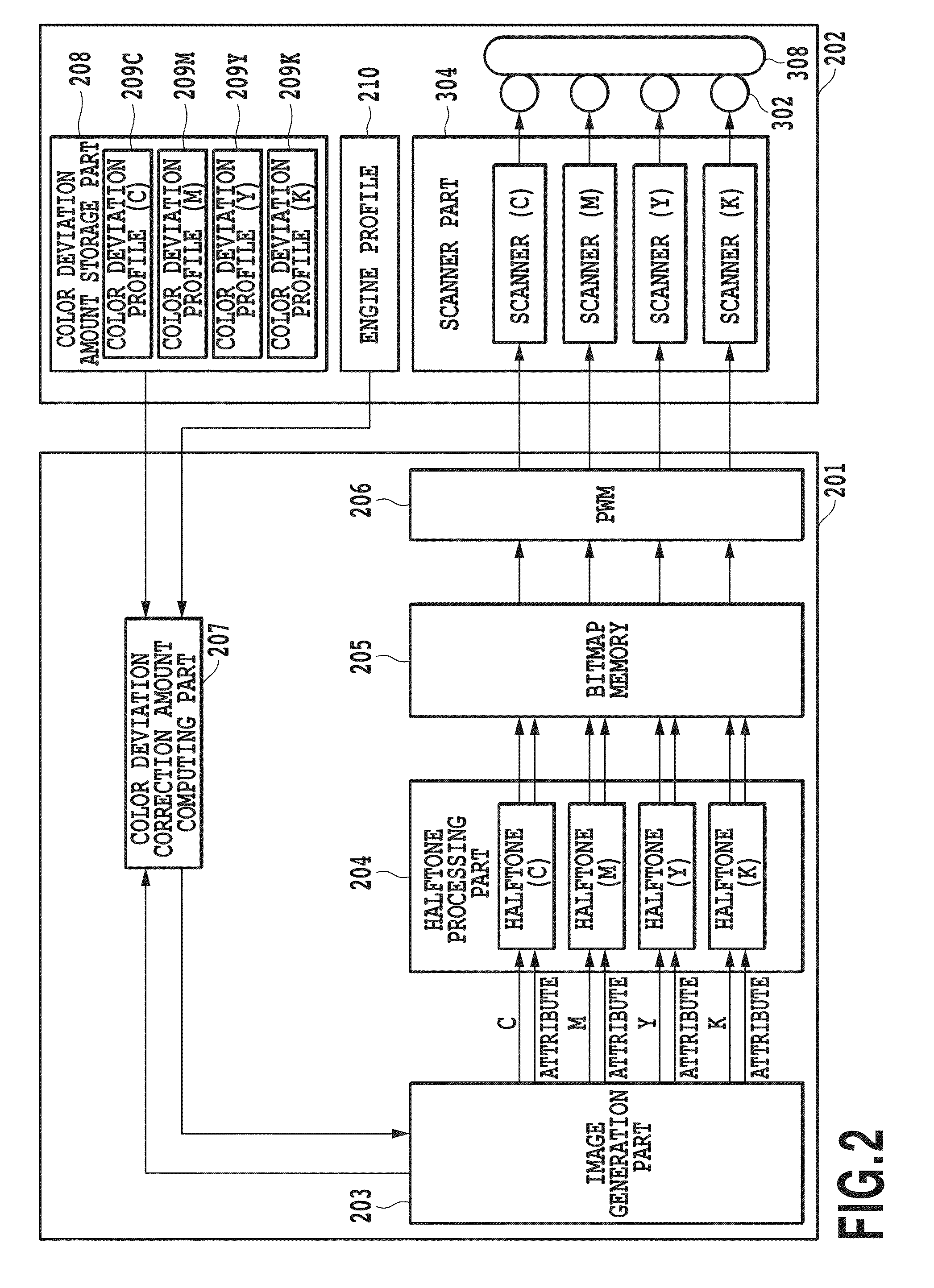
[0038]FIG. 2 is a block diagram illustrating the configuration of an image formation apparatus according to Embodiment 1 of the present invention, the configuration being related to electrostatic latent image formation. The image formation apparatus includes an image processing unit 201 and an image forming unit 202. To give an overall process, the image processing unit 201 generates bitmap image data and performs halftone processing on the bitmap image data, and the image forming unit 202 forms an image on a recording medium based on the data from the image processing unit 201. Constituents in FIG. 2 will be described later.

[0039]FIG. 3 is a cross-sectional view of a tandem color image formation apparatus using an intermediate transfer body 308, as an example of an electrophotographic color image formation apparatus. Using FIG. 3, a description is given of operation of the image forming unit 202 of the ...

embodiment 2

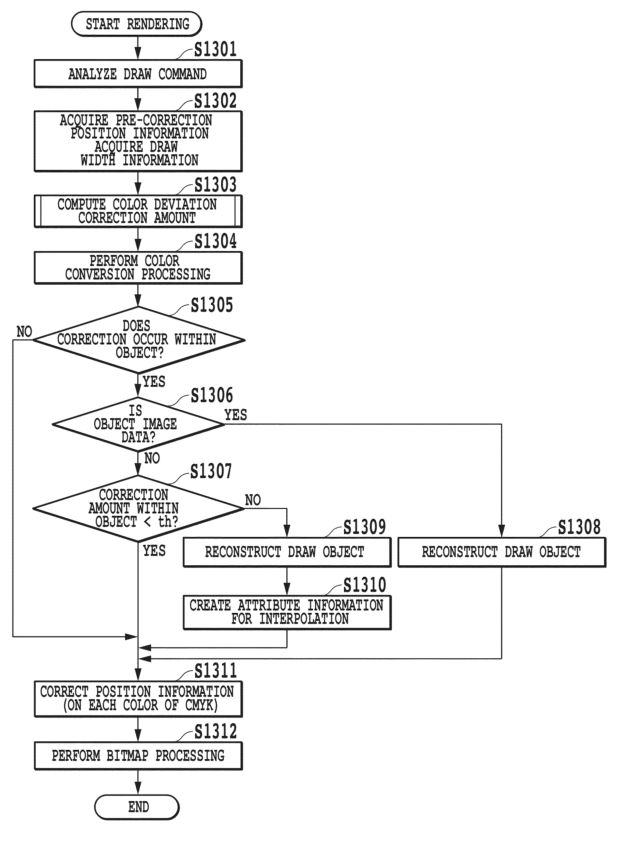
[0093]In the first embodiment of the present invention described above, generation of a step in image data to be drawn is avoided by performing color deviation correction on a draw object basis and performing an offset on a draw object basis. However, when the color deviation correction is performed on a draw object basis, a color deviation may possibly occur within the same object, depending on how much the scan line inclines or curves. Particularly, when the draw object is large in the main scanning direction, such a phenomenon is very likely to occur.

[0094]A second embodiment of the present invention takes this problem into consideration, and determines, based on the width of a draw object, whether one-pixel-basis color deviation correction, namely an offset, occurs within the draw object. Further, when an offset occurs, whether to perform an offset within the draw object is determined based on the characteristics of the draw object and the difference in the correction amount wit...

embodiment 3

[0119]In the first and second embodiments of the present invention described above, the image formation apparatus performs processing for color deviation correction. On the other hand, recent systems often perform print processing in the following manner. Specifically, a computer device (an image processing apparatus) or the like communicatively connected to an image formation apparatus performs the rendering processing and the halftone processing, and sends the image formation apparatus the print data obtained by the halftone processing. In a third embodiment of the present invention, a case where color deviation correction processing is performed by image formation processing on a host computer is described.

[0120]Such color deviation correction processing can be performed by the image formation processing on the host computer when the host computer performs the same processing as the processing performed by the image processing units 201 and 1101 described in detail in the first a...


PUM


Abstract

A problem in conventional electrical color deviation correction is that an awkward step is generated at a border where a pixel is offset by one-pixel-basis correction. Although such a step can be cancelled by less-than-one-pixel-basis correction, this smoothing process in turn generates unevenness in density. To solve these problems, in electrical color deviation correction, a draw command is analyzed to specify a draw position for color deviation correction for each of draw objects. Then, the object is drawn at the specified draw position, and an offset for color deviation correction is performed on an object basis.

Description

BACKGROUND OF THE INVENTION[0001]1. Field of the Invention[0002]The present invention relates to an image processing technique, and particularly to color deviation correction in a sequential transfer of images of multiple colors formed by developing units provided for the respective multiple colors.[0003]2. Description of the Related Art[0004]To achieve high speed image formation, many recent electrophotographic color image formation apparatuses include the same number of developing devices and photoconductors as the number of color materials and employ a system in which images of different colors are sequentially transferred to an image transport belt and then to a recording medium.[0005]Using such a system (i.e., a tandem system) can drastically reduce throughput time, but on the other hand generates problems attributable to factors such as nonuniformity and poor attachment position accuracy of lenses of a deflection scanner and poor attachment position accuracy of the deflection ...

Claims


Application Information

Patent Timeline
Patent Type & Authority Patents(United States)
IPC IPC(8): G06F15/00G06K1/00
CPCH04N1/58H04N1/506H04N1/56
Inventor NAGAI, JUN
Owner CANON KK
Learn More