

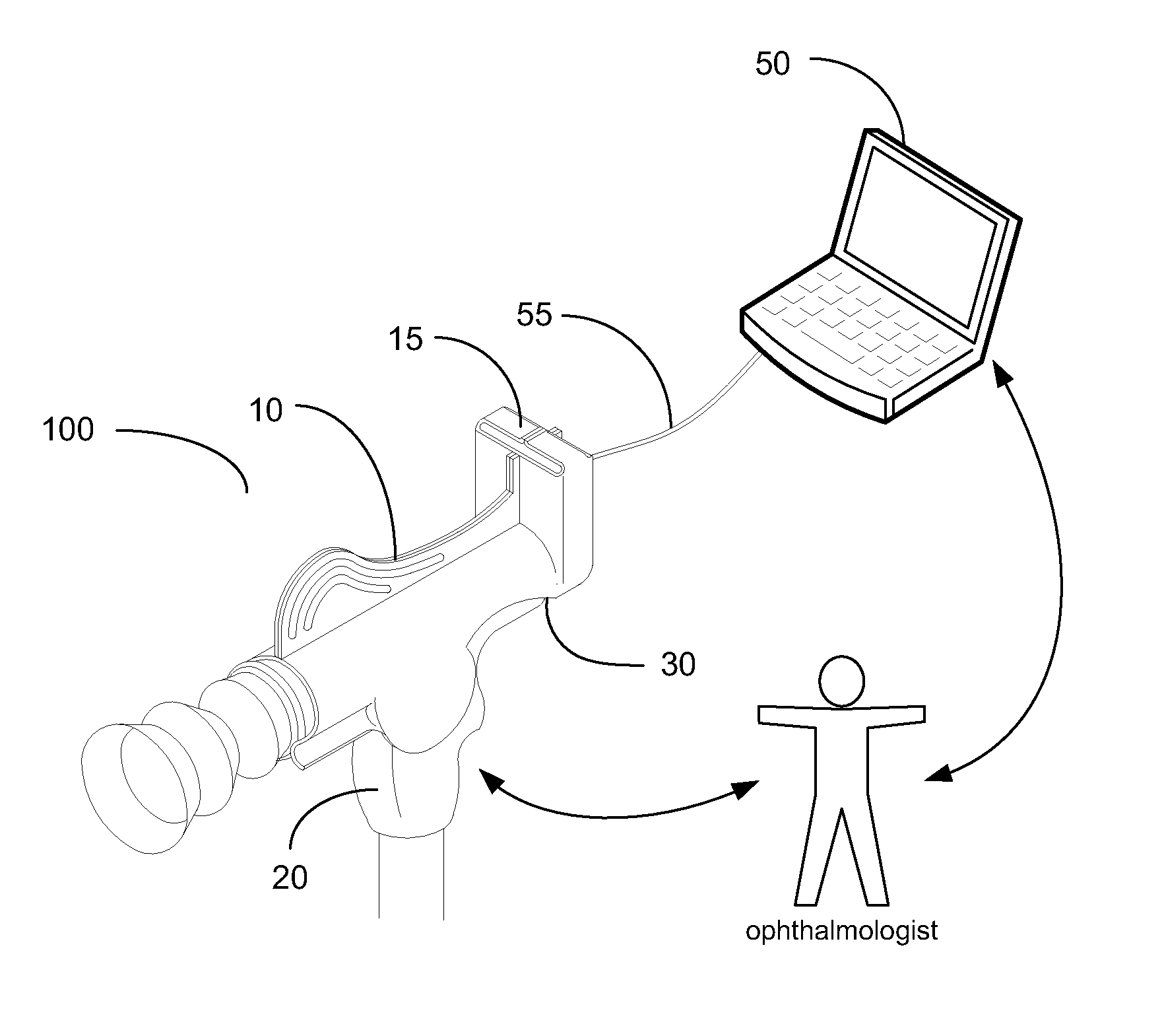
Ophthalmological Diagnostic System
a diagnostic system and ophthalmology technology, applied in the field of ophthalmology, can solve the problems of undesirable camera equipment, unfavorable doctor's image capture, and inability of doctors to transport bulky and expensive equipment to view and photograph the eye,
- Summary
- Abstract
- Description
- Claims
- Application Information
AI Technical Summary
Benefits of technology
Problems solved by technology
Method used
Image

Examples
Embodiment Construction
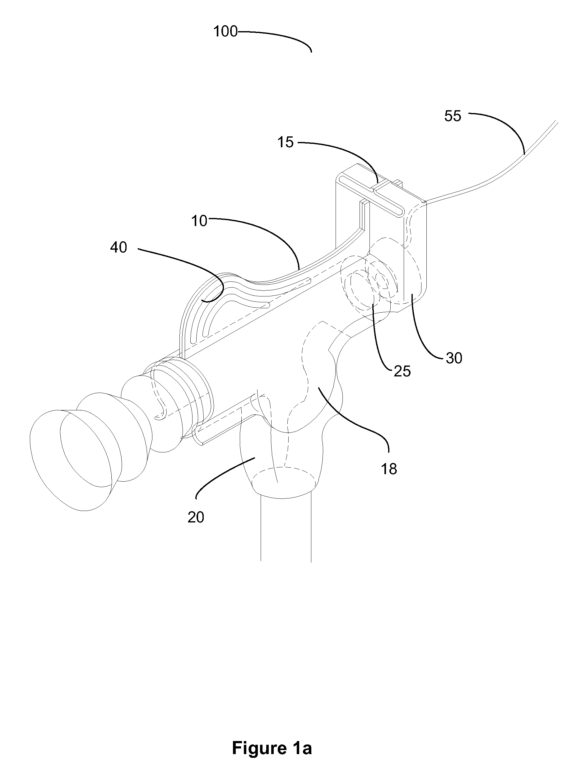
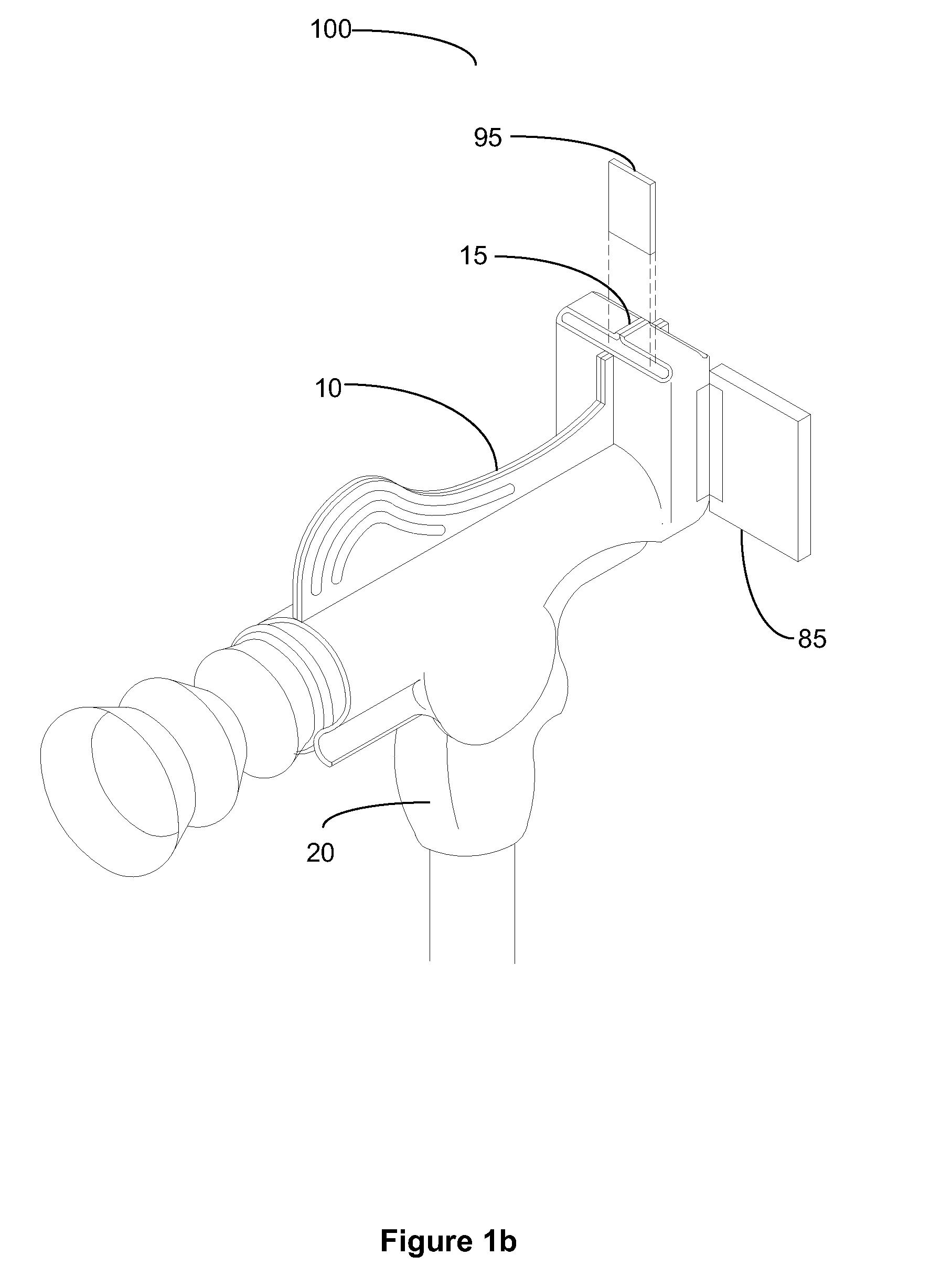
[0035]For the purpose of promoting an understanding of the present invention, references are made in the text to exemplary embodiments of an ophthalmologic diagnostic system, only some of which are described herein. It should be understood that no limitations on the scope of the invention are intended by describing these exemplary embodiments. One of ordinary skill in the art will readily appreciate that alternate but functionally equivalent components, materials, designs, and equipment may be used. The inclusion of additional elements may be deemed readily apparent and obvious to one of ordinary skill in the art. Specific elements disclosed herein are not to be interpreted as limiting, but rather as a basis for the claims and as a representative basis for teaching one of ordinary skill in the art to employ the present invention.
[0036]It should be understood that the drawings are not necessarily to scale; instead, emphasis has been placed upon illustrating the principles of the inve...
PUM
 Abstract
Description
Claims
Application Information