
Woven Preform, Composite, and Method of Making Thereof

a technology of fiber reinforced composites and preforms, applied in the field of preforms, can solve the problems of not having the same materials or comparable physical properties, increasing production costs as well as overall weight, and achieving the effect of maximizing strength and stiffness

Active Publication Date: 2011-04-14
ALBANY ENGINEERED COMPOSITES
View PDF32 Cites 8 Cited by
  • Summary
  • Abstract
  • Description
  • Claims
  • Application Information

AI Technical Summary

Benefits of technology

[0014]Accordingly, one object of the present invention is to have the reinforcing fiber follow the principal directions of the window frame, which are parallel to the perimeter and normal to the local radius of curvature, as shown in FIG. 3(b). This results in a preform with uniform strength and stiffness with respect to the principal coordinate system, and maximizes strength and stiffness in the principal directions of the resultant structure.
[0016]Yet another object of the present invention is to provide a method of forming a three dimensional preform that has reduced weight and / or improved performance when compared to prior art designs.

Problems solved by technology

Typically, however, they will not be of the same materials or have comparable physical, chemical, thermal or other properties, since a usual objective sought in using composites in the first place is to achieve a combination of characteristics in the finished product that is not attainable through the use of one constituent material alone.
Traditional metallic window frames cannot be used for this application because of differences between the coefficients of thermal expansion of the composite fuselage and the metallic frame.
These barrier plies increase cost of production as well as the overall weight.
The upstanding leg 20 is a particularly difficult feature to incorporate into a composite design because of the oval shape of the frame 10.
These darts, however, degrade the strength and stiffness of the composite if they are not reinforced.
This approach, however, leads to two potential problems.
First, a quasi-isotropic layup only has uniform stiffness properties.

Method used


Image

  • Woven Preform, Composite, and Method of Making Thereof
  • Woven Preform, Composite, and Method of Making Thereof
  • Woven Preform, Composite, and Method of Making Thereof

Examples


Embodiment Construction

[0032]The instant invention will now be described more fully hereinafter with reference to the accompanying drawings, in which preferred embodiments of the invention are shown. This invention may, however, be embodied in many different forms and should not be construed as limited to the illustrated embodiments set forth herein. Rather, these illustrated embodiments are provided so that this disclosure will be thorough and complete, and will fully convey the scope of the invention to those skilled in the art.

[0033]In the following description, like reference characters designate like or corresponding parts throughout the figures. Additionally, in the following description, it is understood that such terms as “upper,”“lower,”“top,”“bottom,”“first,”“second,” and the like are words of convenience and are not to be construed as limiting terms.

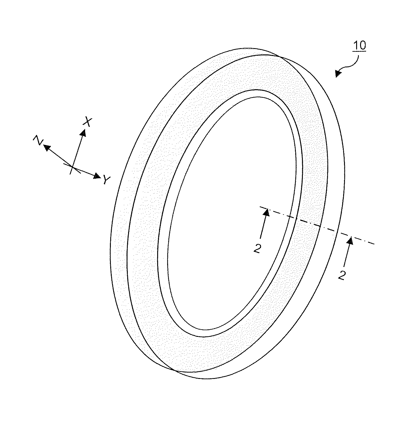
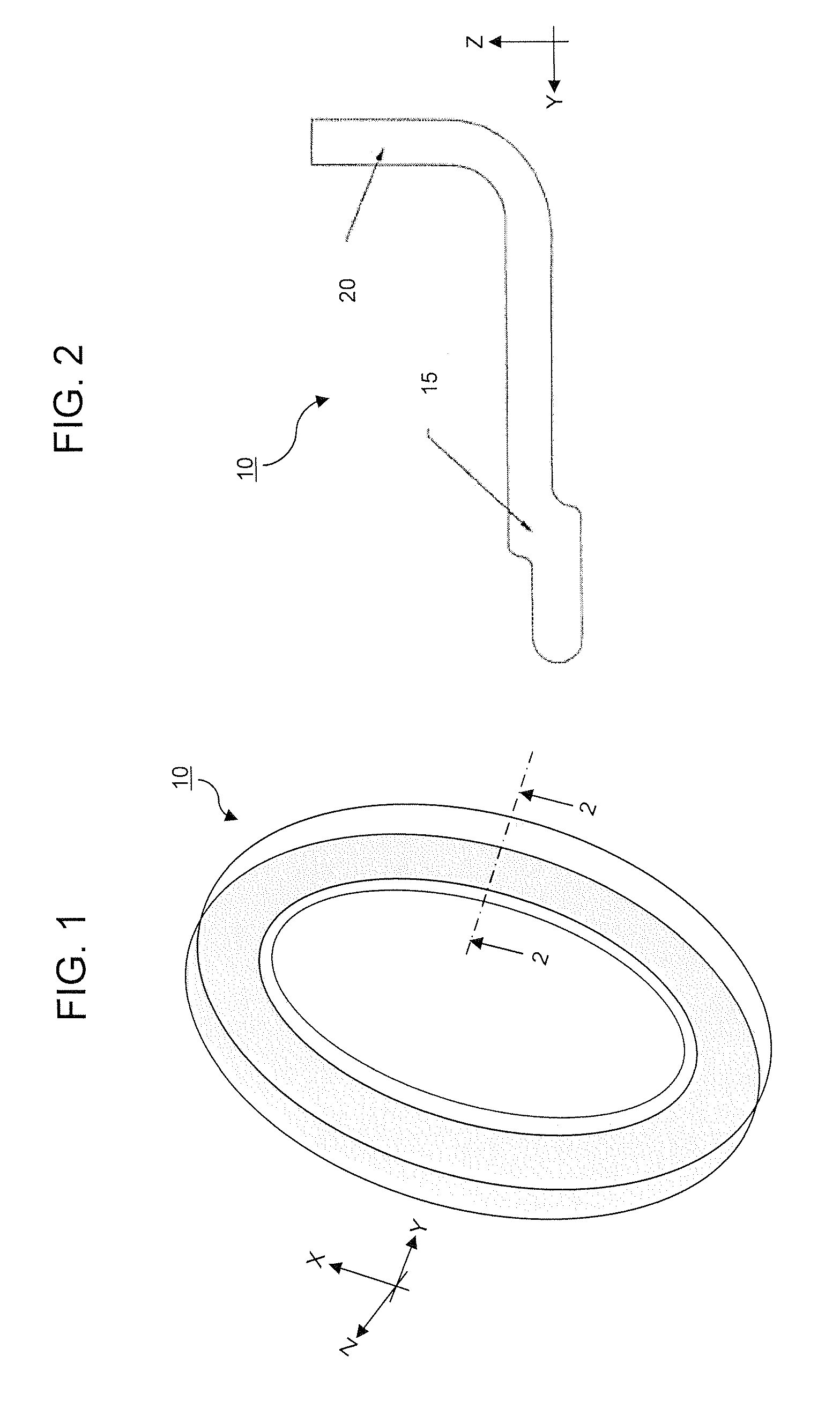
[0034]Turning now to the figures, the invention according to one embodiment is a method of fabricating a three dimensional woven preform for use in...


PUM

PropertyMeasurementUnit
Angleaaaaaaaaaa

Abstract

A three dimensional woven preform, a fiber reinforced composite incorporating the preform, and methods of making thereof are disclosed. The woven preform includes two or more warp steered fabrics. The warp steered fabrics include a darted portion and an un-darted portion. The darted portions of the warp steered fabrics are joined to un-darted portions of one another so as to provide continuous fiber in the circumferential and radial directions of all portions of the preform. An un-darted portion in one steered fabric reinforces a darted portion in the other. The warp steered fabrics can be woven on a loom equipped with a differential take-up mechanism. The warp steered fabrics can be single or multilayer fabrics. The final preform can be a portion of an aircraft window frame.

Description

CROSS REFERENCE TO RELATED APPLICATION[0001]This application claims priority benefits to U.S. Provisional Patent Application No. 61 / 247,777 filed Oct. 1, 2009, the entire disclosure of which is incorporated herein by reference.BACKGROUND OF THE INVENTION[0002]1. Field of the Invention[0003]This invention generally relates to fiber reinforced composites and particularly relates to preforms having woven strips of material used in reinforced composite materials, which can be woven flat and formed into their final shape, the final shape having reinforcement in two or more directions.[0004]2. Incorporation by Reference[0005]All patents, patent applications, documents, references, manufacturer's instructions, descriptions, product specifications, and product sheets for any products mentioned herein are incorporated herein by reference, and may be employed in the practice of the invention.[0006]3. Description of the Prior Art[0007]The use of reinforced composite materials to produce struct...

Claims


Application Information

Patent Timeline
IPC IPC(8): B32B5/26D03D15/00B05D1/00B29C45/02D03D41/00D03D3/00
CPCB29B11/16B29C70/222B29C70/48B29K2707/04Y10T428/24174D03D49/04D03D49/20D10B2505/02Y10T428/24182D03D3/08B29L2031/005Y10T442/3179Y10T442/3187Y10T442/3195D03D11/02D03D25/005D03D41/004
Inventor GOERING, JONATHAN
Owner ALBANY ENGINEERED COMPOSITES
Learn More