
Magnetic assisted plastic composite welding for weld line fiber crossover

Active Publication Date: 2021-02-11
GM GLOBAL TECH OPERATIONS LLC
View PDF0 Cites 0 Cited by
  • Summary
  • Abstract
  • Description
  • Claims
  • Application Information

AI Technical Summary

Benefits of technology

The present invention is about a welding tool that uses a magnetic field to improve the weld. The tool contains magnets that are either incorporated in the tool or external to it, and the tool is made of magnetically permeable material. The magnetic field helps to orient the magnetic fibers across the weld plane, making the resulting weld stronger and stiffer. The fibers have an aspect ratio greater than 1 to allow for magnetic field orientation, and may include a coating made of magnetic material. The energy applied to the workpieces can be infrared energy or ultrasonic acoustic vibrations. The magnetic field is applied to the workpieces so that most of the fibers are angled between 20 degrees and 160 degrees relative to the weld plane to maximize stiffness and strength of the weld area and the workpieces.

Problems solved by technology

For example, intake manifolds may fail at the weld during a burst test.

Method used


Image

  • Magnetic assisted plastic composite welding for weld line fiber crossover

Examples


Embodiment Construction

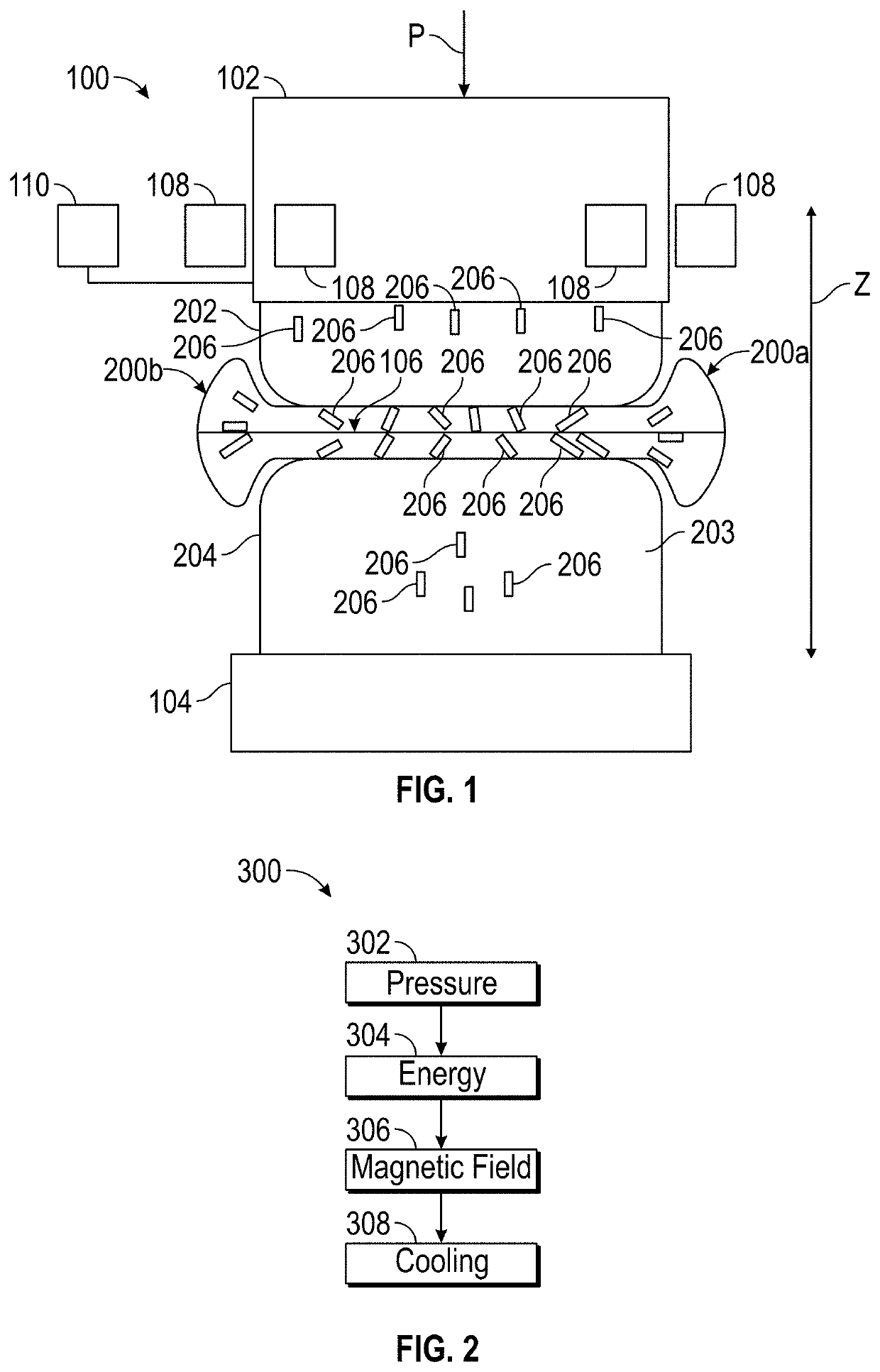
[0014]The following detailed description is merely exemplary in nature and is not intended to limit the application and uses. Furthermore, there is no intention to be bound by expressed or implied theory presented in the preceding introduction, summary or the following detailed description.

[0015]Embodiments of the present disclosure may be described herein in terms of functional and / or logical block components and various processing steps. It should be appreciated that such block components may be realized by a number of hardware, software, and / or firmware components configured to perform the specified functions. For example, an embodiment of the present disclosure may employ various integrated circuit components, e.g., memory elements, digital signal processing elements, logic elements, look-up tables, or the like, which may carry out a variety of functions under the control of one or more microprocessors or other control devices. In addition, those skilled in the art will apprecia...


PUM

PropertyMeasurementUnit
Angleaaaaaaaaaa
Angleaaaaaaaaaa
Angleaaaaaaaaaa

Abstract

A welding method includes: moving a welding head toward a plurality of workpieces, wherein each of the plurality of workpieces includes a polymeric composite, the polymeric composite includes a polymer matrix and a plurality of fibers, and each of the fibers includes a magnetic material; applying a joining pressure to the workpieces with the welding head; applying energy to the plurality of workpieces to melt an interface between the plurality of workpieces, wherein a weld plane is defined at the interface between the plurality of workpieces; and applying a magnetic field to the plurality of workpieces to change an orientation of the plurality of fibers relative to the polymer matrix in the weld area so that the fibers in a weld area are at an angle relative to the weld plane.

Description

INTRODUCTION[0001]The present disclosure relates to magnetic assisted plastic composite welding for weld line fiber crossover.[0002]Plastic welding is a process for joining two or more workpieces. In general, welding may include the application of heat and pressure to at least two workpieces in order to coalesce the workpieces. Numerous welding processes have been developed over the years.SUMMARY[0003]The present disclosure relates to magnetic assisted plastic composite welding for weld line fiber crossover. This method combines a magnetic field with the welding process of plastic composites to orient fibers across the weld and strengthen the weld. The weld is the structurally weakest area of a welded fiber reinforced plastic composite part. For example, intake manifolds may fail at the weld during a burst test. Welding of short fiber plastic composites induces fiber flowing (squeeze out) and a narrow (about 100 μm) weak weld layer with fibers oriented in the weld plane. The present...

Claims


Application Information

Patent Timeline
IPC IPC(8): B29C65/00B23K20/10B23K31/00B29C65/08B29C65/14
CPCB29C66/03B23K20/106B23K31/003B23K2103/42B29C65/1412B29C66/7212B29C65/08B29C65/02B29C66/0342B29C66/1122B29C66/3034B29C66/341B29C66/348B29C66/73921B29C66/81422B29C66/8322B29K2307/04B29K2309/08B29K2305/08
Inventor JONES, MARIE-CHRISTINESGRICCIA, NIKKI
Owner GM GLOBAL TECH OPERATIONS LLC
Learn More