Tong Gear Shift System

a transmission system and gear shift technology, applied in the direction of gearing control, belt/chain/gearing, toothed gearing, etc., can solve the problems of gear teeth being worn excessively, gear teeth often affecting the smooth meshing of the gears, and gear teeth often rubbing

Active Publication Date: 2011-04-21
MCCOY CORPORATION
View PDF5 Cites 29 Cited by
  • Summary
  • Abstract
  • Description
  • Claims
  • Application Information

AI Technical Summary

Problems solved by technology

However, because power tongs do not have complex gear meshing mechanisms and because the gears of the transmission may be stationary when the shift occurs, the largely flat top surface on the teeth of such gears often interferes with the gears meshing smoothly.
However, this often leads to the “grinding” of the gears and excessive wear on the gear teeth, particularly if the motor is run at too high of a speed during meshing.

Method used


Image

  • Tong Gear Shift System
  • Tong Gear Shift System
  • Tong Gear Shift System

Examples


Embodiment Construction

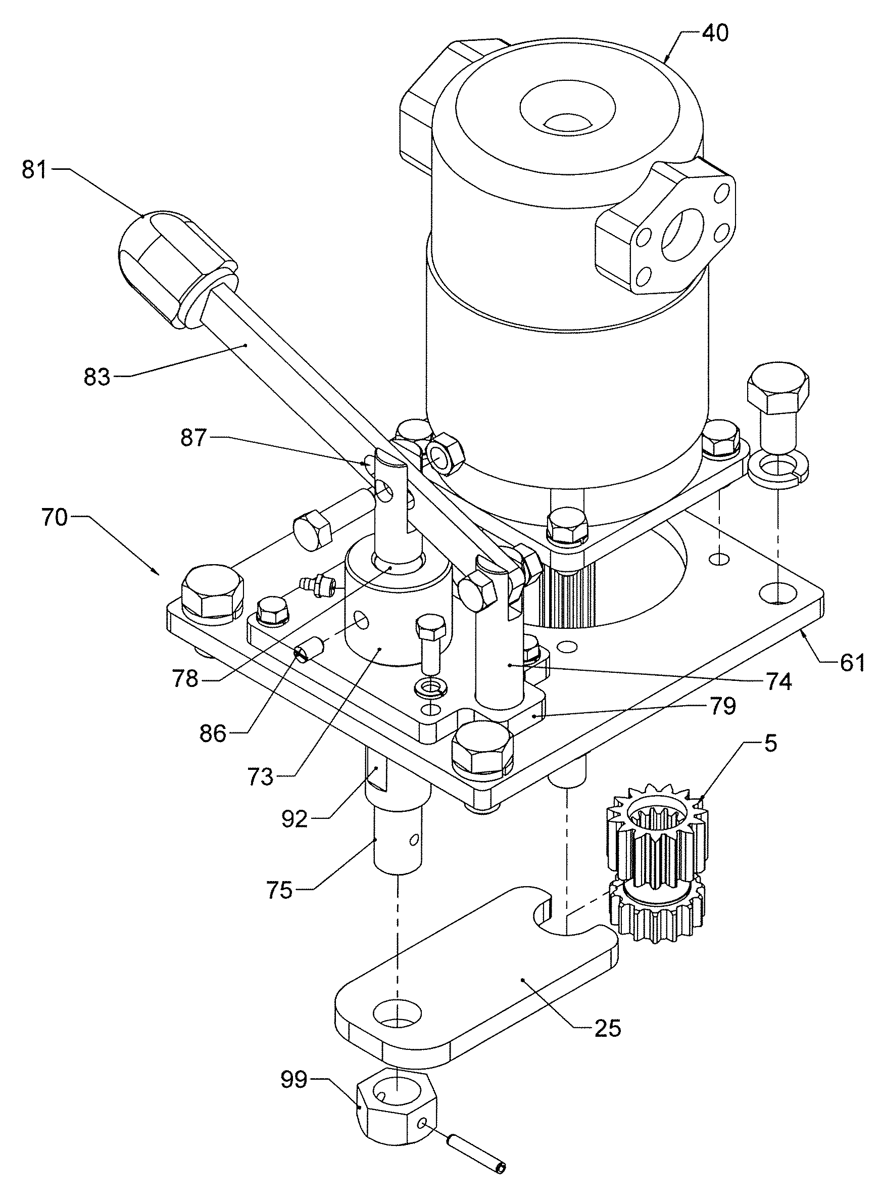
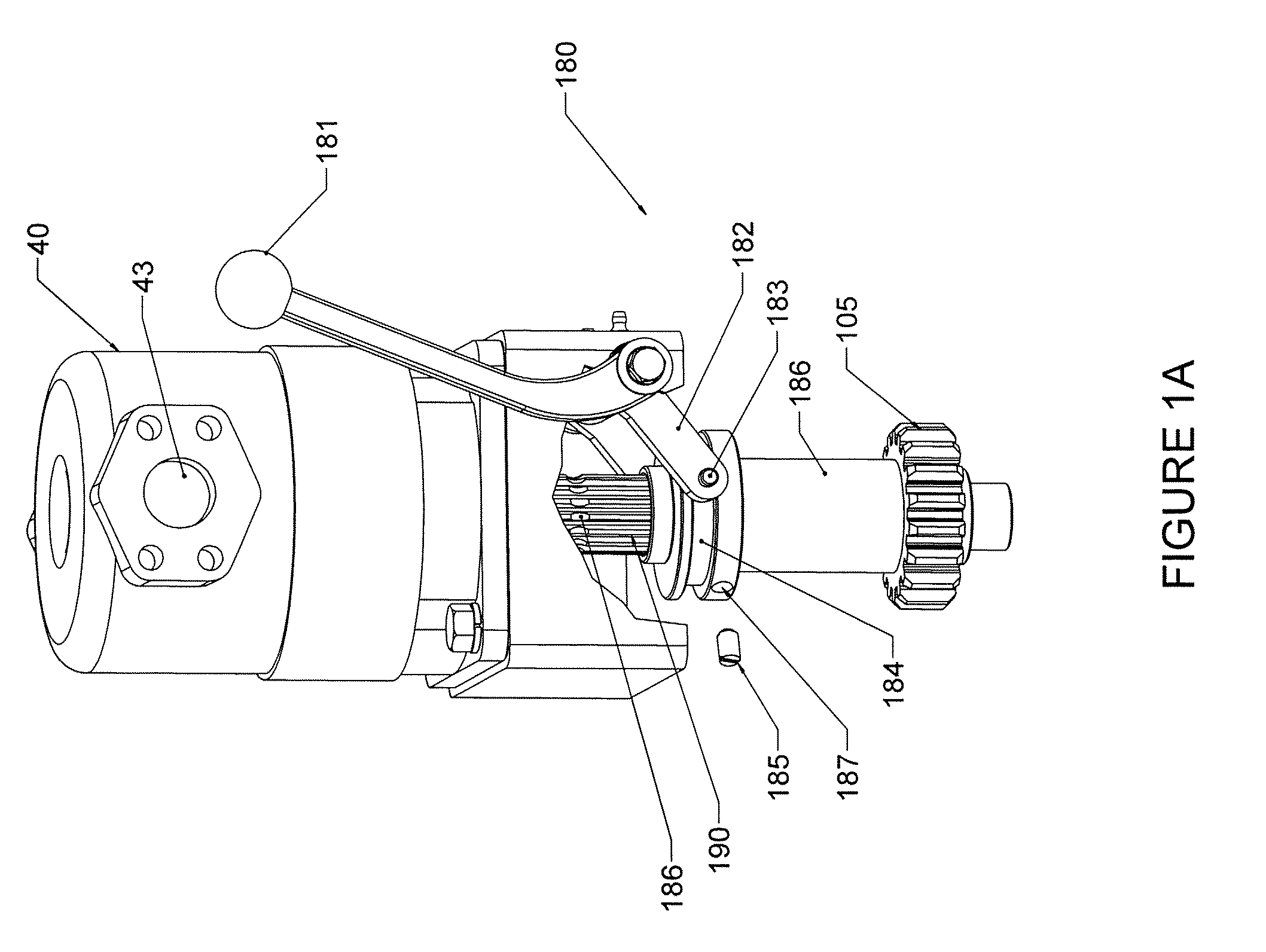
[0006]One embodiment of the invention is a power tong having a ring gear, a gear train, a motor and a gear shift mechanism. The gear shift mechanism further includes a linear actuator and a shift arm connect to the linear actuator. A drive gear is positioned on a drive shaft extending from the motor and this drive gear includes an upper and lower set of drive teeth having beveled top portions. The shift arm engages the drive gear between the upper and lower set of drive teeth and movement of the linear actuator causes the drive gear to engage one of at least two gears in the gear train.

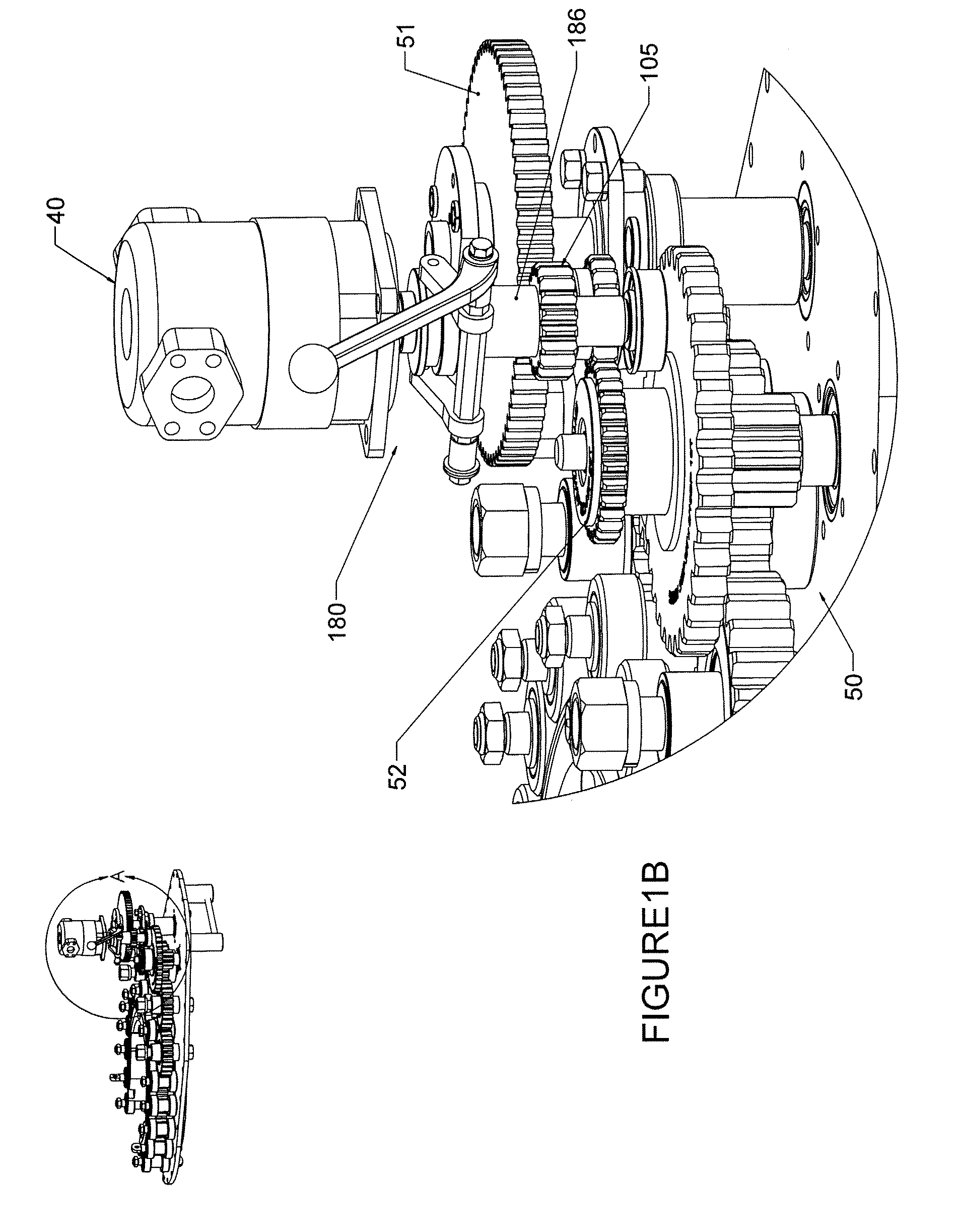
[0007]Another embodiment of the invention includes a tong body having a top plate and a bottom plate forming a cavity there between. A ring gear and gear train are positioned within the cavity and the gear train includes a high speed and a low speed gear. A motor has a drive shaft extending directly into said cavity and the drive shaft includes a drive gear connected thereon which selectively engages ...


PUM


Abstract

A power tong having a ring gear, a gear train, a motor and a gear shift mechanism. The gear shift mechanism further includes a linear actuator and a shift arm connect to the linear actuator. A drive gear is positioned on a drive shaft extending from the motor and this drive gear includes an upper and lower set of drive teeth having beveled top portions. The shift arm engages the drive gear between the upper and lower set of drive teeth and movement of the linear actuator causes the drive gear to engage one of at least two gears in the gear train.

Description

[0001]This application claims the benefit under 35 USC §119(e) of U.S. provisional application No. 60 / 914,562 filed Apr. 27, 2007, which is incorporated by reference herein in its entirety.I. FIELD OF INVENTION [0002]The present invention relates to devices for applying torque to tubular members such as drill pipe. In a particular embodiment, the invention relates to transmission systems in power tongs.II. BACKGROUND OF INVENTION [0003]Many devices such as power tongs employ a transmission or gear train having different gears (or sets of gears) for operating at different speeds and torque ratios. An example of such a power tong is seen in U.S. Pat. No. 4,631,987, which is incorporated by reference herein in its entirety. In order to run the gear train at different speeds, the power source (e.g., a motor shaft) must selectively engage the different gears in the gear train. This typically entails selectively bringing a drive gear on the motor shaft into engagement with the appropriate...

Claims


Application Information

Patent Timeline
Patent Type & Authority Applications(United States)
IPC IPC(8): F16H59/02
CPCE21B19/164Y10T74/19251F16H55/0873F16H3/30
Inventor BUCK, DAVID A.GRAVOUIA, MARK
Owner MCCOY CORPORATION
Why Eureka
Try Eureka