Eureka AIR delivers breakthrough ideas for toughest innovation challenges, trusted by R&D personnel around the world.

Device for handling powder for a welding apparatus

a welding apparatus and powder technology, applied in welding apparatus, evacuating shielding, manufacturing tools, etc., can solve the problems of troublesome installation and handling, complicated equipment in the form of pressure containers and other for the transfer of powder from the reservoir to the drop release container, and high cos

Active Publication Date: 2011-04-21
ESAB AB
View PDF66 Cites 2 Cited by
  • Summary
  • Abstract
  • Description
  • Claims
  • Application Information

AI Technical Summary

Benefits of technology

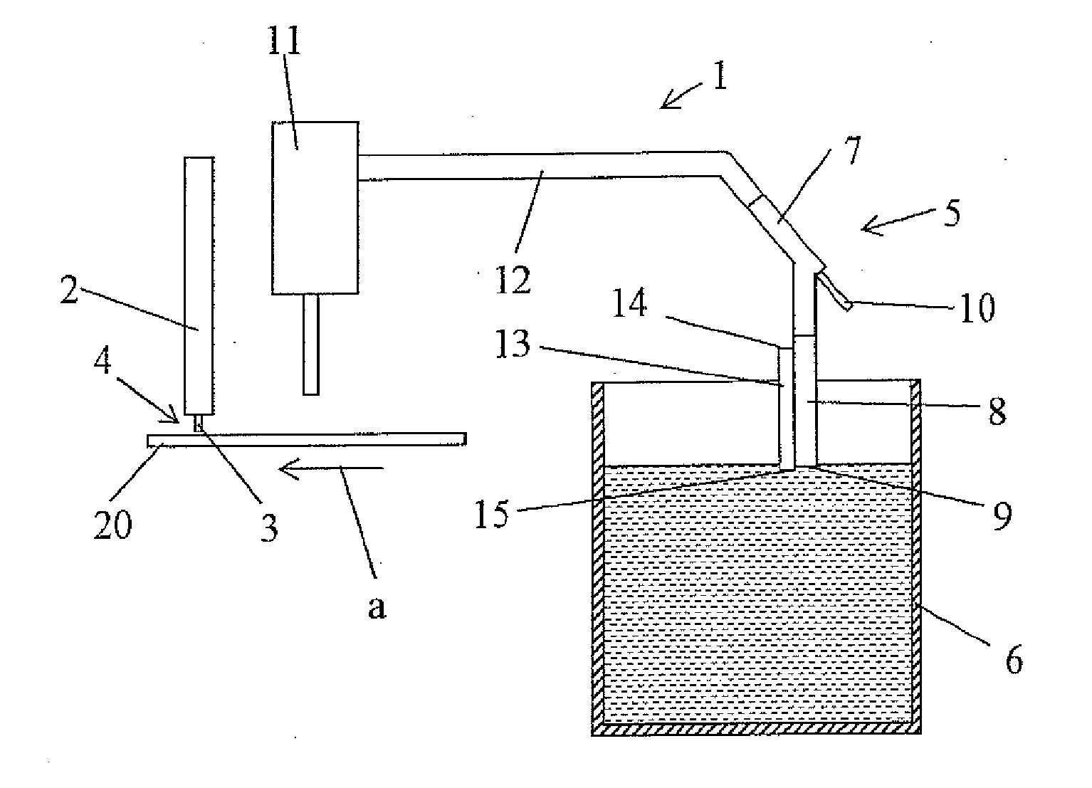
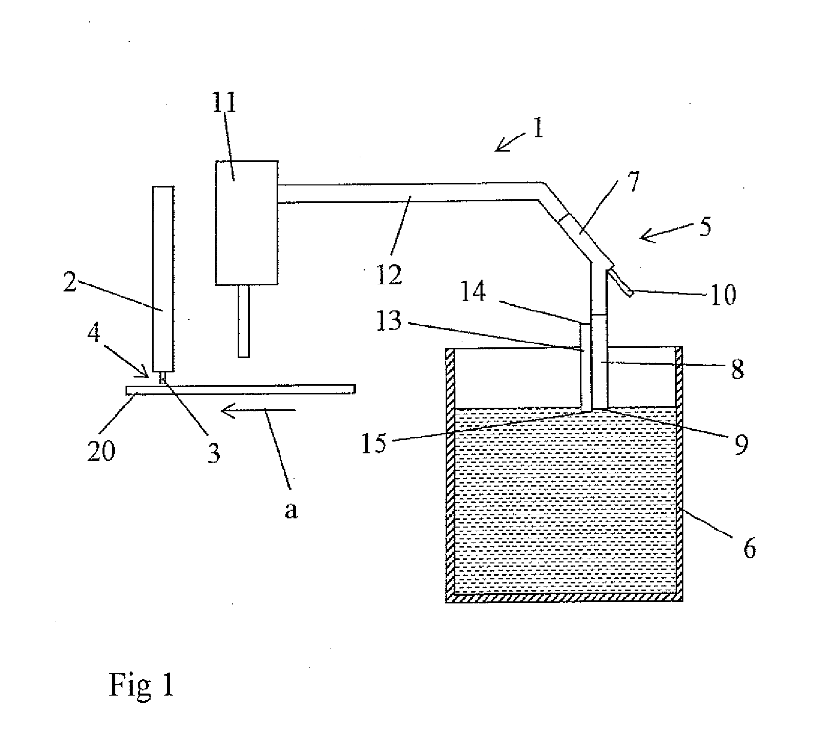
[0008]According to a first aspect of the invention a welding device is provided for powder welding, which comprises a welding head for transportation of at least one welding electrode to a welding area, and a powder transportation device for transportation of powder from a container to the welding area, wherein the powder transportation device comprises at least a first pipe which in a first end has an opening which is arranged to be placed in the container to transport powder from the container. The welding device is characterized in that the powder transportation device comprises at least a first ejector which is connected to the second end of the first pipe and which is arranged to transport powder from the container via the first pipe using pressurized gas. An air supply pipe is arranged with one of its openings adjacent to the opening in the first end of the first pipe for transportation of air to the opening of the first pipe. In this way air supply is secured to the first pipe and the problems with bad suction due to the air flow being too low is thereby avoided.
[0009]With a powder transportation device according to the invention suction of welding powder directly from a transportation container is enabled. This facilitates the powder handling compared to when devices according to the prior art are used.
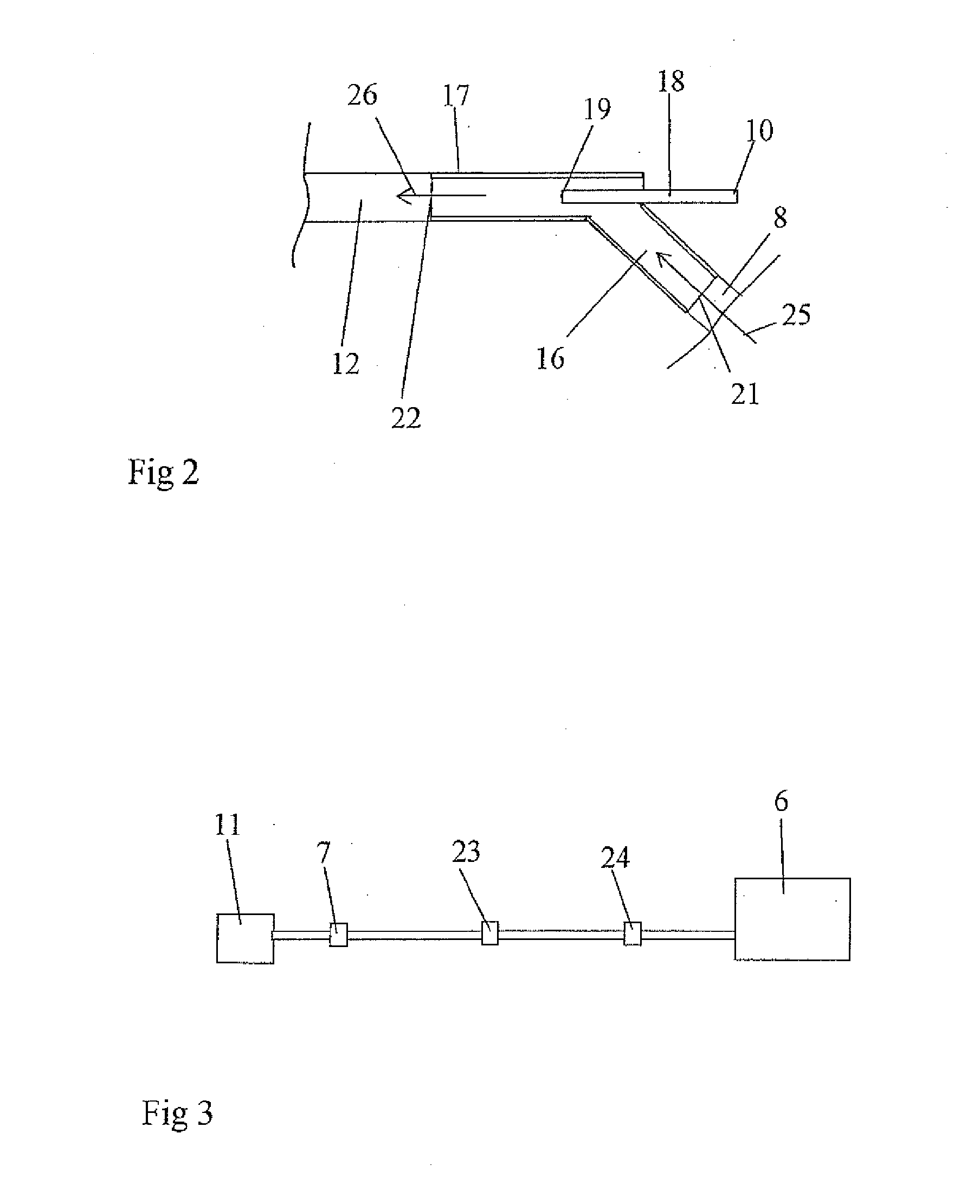
[0011]The first ejector may comprise an inlet, an outlet, and wherein the powder transportation device comprises a second pipe which is arranged fixed in the outlet of the first ejector and arranged to transport powder from the first ejector, wherein the second end of the first pipe is arranged fixed in the inlet of the first ejector. The ejector is preferably arranged adjacent to the container for fluxing agent so that the distance which fluxing agent has to be sucked is kept relatively short.
[0012]The inlet of the first ejector may define an inlet direction and the outlet of the first ejector may define an outlet direction, wherein the inlet direction forms an angle with the outlet direction. By arranging the outlet direction at an angle with the inlet direction the supply of pressurized gas to the orifice is facilitated. It is of course possible within the scope of the invention to let the inlet direction be parallel to the outlet direction.

Problems solved by technology

Another problem with the present welding installations is that the equipment in the form of pressure containers and other for transfer of powder from the reservoir to the drop release container is complicated, expensive and troublesome to install and handle.

Method used


Image

  • Device for handling powder for a welding apparatus
  • Device for handling powder for a welding apparatus
  • Device for handling powder for a welding apparatus

Examples


Embodiment Construction

[0022]In the following description of preferred embodiments of the invention similar parts in different figures will be denoted by the same reference numeral.

[0023]FIG. 1 shows schematically a welding device 1 for powder welding according to an embodiment of the present invention. The welding device 1, comprises a welding head 2, for feeding at least one welding electrode 3 to a welding area 4 on a work piece 20, and a powder transportation device 5 for transportation of fluxing agent in powder form from a container 6 to the welding area 4. The powder transportation device 5 comprises an ejector 7 and a first pipe 8, which in a first end has an opening 9 which is arranged to be placed in the container to transport powder from the container 6, and which in the second end is connected to the ejector 7. The powder transportation device comprises also a drop release container 11 and a second pipe 12 which is arranged between the ejector 7 and the drop release container 11. The ejector 7...


PUM

PropertyMeasurementUnit
inner diameteraaaaaaaaaa

Abstract

A welding device for powder welding is described, which comprises a welding head for transportation of at least one welding electrode to a welding area, and a powder transportation device for transportation of powder from a container to the welding area. The powder transportation device comprises at least a first pipe which at a first end has an opening which is arranged to be placed in the container in order to transport fluxing agent from the container. The powder transportation device comprises at least a first ejector which is connected to the second end of the first pipe and which is arranged to transport powder from the container via the first pipe using pressurized gas.

Description

TECHNICAL FIELD[0001]The present invention relates to a device and a method for handling powder for a welding apparatus for powder welding. More specifically, the present invention relates to a device and a method for transfer of powder from a container to a welding area in powder welding.DESCRIPTION OF THE PRIOR ART[0002]The present invention relates to powder welding which is a well known welding technique in which a flux compound in powder form is applied to a surface on which welding is to be performed. At least one welding electrode is moved to the surface where the powder has been applied and a voltage is applied between said at least one welding electrode and the surface. It is desirable that the welding may be performed under powder within the entire welding area.[0003]In present welding installations for powder welding, which are adapted for welding with a large speed a lot of powder is consumed per time unit. The present welding installations comprise at least one containe...

Claims


Application Information

Patent Timeline
Patent Type & Authority Applications(United States)
IPC IPC(8): B23K9/32
CPCB23K9/324
Inventor LARSSON, ROLF GOSTAJOHANSSON, BJORN
Owner ESAB AB
Why Eureka
Eureka Blog
Learn More