Liquid ejecting apparatus

a liquid ejecting and liquid technology, applied in the direction of printing, other printing apparatus, etc., can solve the problems of large amount of liquid within the tube, large amount of liquid waste, and inability to properly print images, etc., to achieve the effect of ejecting liquid and suppressing liquid

Active Publication Date: 2011-04-21
SEIKO EPSON CORP
View PDF3 Cites 16 Cited by
  • Summary
  • Abstract
  • Description
  • Claims
  • Application Information

AI Technical Summary

Benefits of technology

[0016]If such a cap member is provided, it is possible to suppress the liquid from drying through the ejection nozzle by bringing the cap member into contact with the nozzle surface during periods when liquid is not being ejected. Furthermore, even in the case w

Problems solved by technology

As a result, areas of high pigment density and areas of low pigment density occur within the ink, which makes it impossible to print images properly.
Although settling occurring in the flow channels does improve to an extent by the time the liquid has passed through the flow channels and reached the ejection head, there are cases where the settling has advanced to a point where it cannot be corrected; in such a case, it is necessary to discharge not only the liquid within the ejection head, but also the liquid within the flow channels, which is problematic in that a large amount of liquid is wasted.
In particular, with a type of liquid ejecting apparatus in which a dedicated receptacle that holds the liquid is p

Method used


Image

  • Liquid ejecting apparatus
  • Liquid ejecting apparatus
  • Liquid ejecting apparatus

Examples


Embodiment Construction

[0026]Hereinafter, an embodiment of the invention will be described according to the following order in order to clarify the content of the invention.

[0027]A. Apparatus Configuration

[0028]B. Outline of Printing Operations

[0029]C. Standing Ink Management Process According to Embodiment

A. Apparatus Configuration

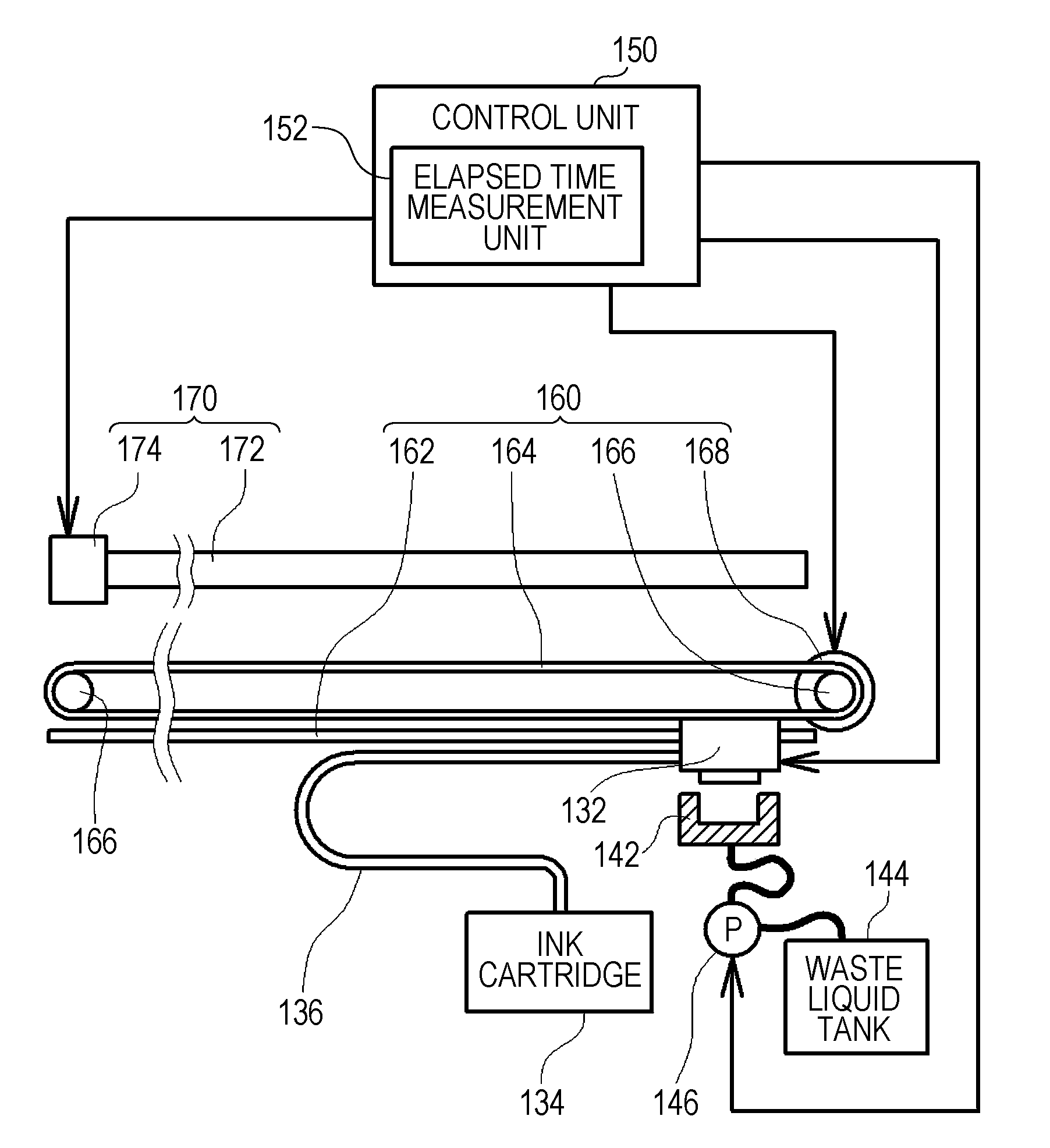
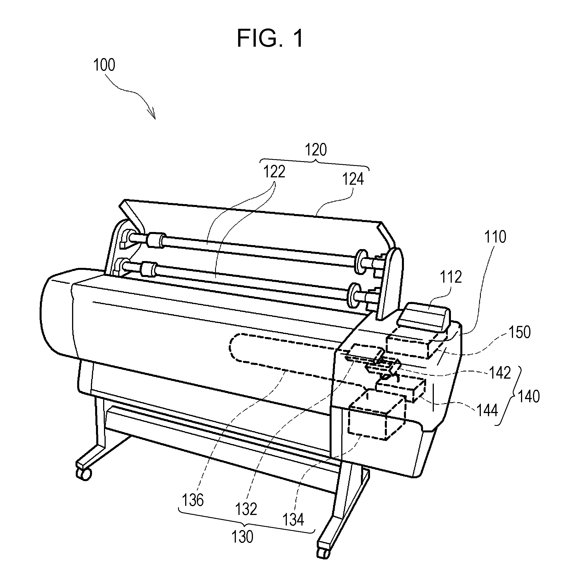
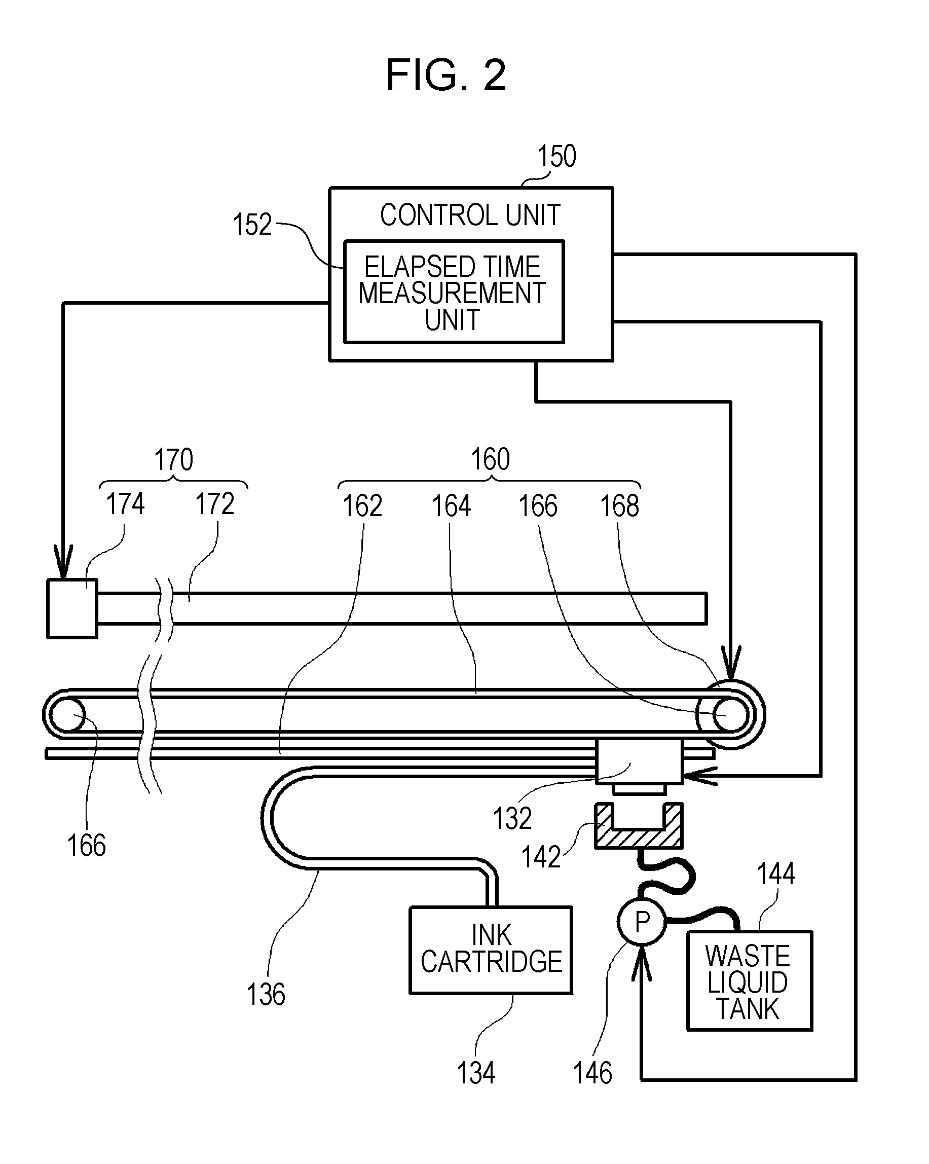
[0030]FIG. 1 is a descriptive diagram illustrating an example of an ink jet printer 100 serving as a liquid ejecting apparatus according to this embodiment. Although the ink jet printer 100 illustrated here is a so-called large format printer (LFP) that prints onto so-called oversized printing paper, such as JIS A1, JIS B1, or the like, the ink jet printer 100 may be a household printer that prints onto smaller-sized printing paper, such as A4, postcard size, or the like.

[0031]As shown in FIG. 1, the ink jet printer 100 is, generally speaking, configured of a main body case 110, a paper supply unit 120 that is provided on the upper surface side of the main body case 110 and int...


PUM


Abstract

A liquid ejecting apparatus that ejects a liquid containing a sedimentary component from an ejection nozzle provided in an ejection head includes: a liquid channel that conducts the liquid to the ejection head; a liquid discharge unit that discharges the liquid from the ejection nozzle. The liquid channel is provided with a first channel region and a second channel region; and the liquid discharge unit discharge a predetermined amount of the liquid from the ejection nozzle in the case where the amount of time that has elapsed a predetermined threshold time.

Description

BACKGROUND[0001]1. Technical Field[0002]The present invention relates to techniques for ejecting liquid from an ejection nozzle.[0003]2. Related Art[0004]Liquid ejecting apparatuses that eject liquid such as ink from an ejection head in which fine ejection nozzles are provided are known. With such a liquid ejecting apparatus, the liquid to be ejected (ink, for example) is held in a dedicated receptacle (an ink cartridge, for example), and the liquid within the receptacle is ejected by supplying that liquid to the ejection head via a flow channel.[0005]Meanwhile, there are situations where sedimentary components are used as components in the liquid to be ejected. For example, in the case of ink, pigments are used in order to increase the so-called climate resistance or improve the color development properties of the ink. Because pigments are suspended rather than dissolved within the carrier (water, alcohol, or the like) of the ink, a pigment will settle within the carrier if the ink...

Claims


Application Information

Patent Timeline
IPC IPC(8): B41J29/38
CPCB41J2/2107B41J2/16532
Inventor HARADA, KOJI
Owner SEIKO EPSON CORP
Why Eureka
Try Eureka