Image Alignment Using Translation Invariant Feature Matching

a technology of invariant feature matching and image alignment, applied in image enhancement, image analysis, instruments, etc., can solve the problems of low resolution image not useful for surveillance applications, bending space at the sides of images, and barrel distortion effects

Active Publication Date: 2011-04-21
LTIMINDTREE LTD
View PDF17 Cites 38 Cited by
  • Summary
  • Abstract
  • Description
  • Claims
  • Application Information

AI Technical Summary

Problems solved by technology

However, to cover wide space, large field view lenses are used resulting in barrel distortion effects on a resultant image which produces bending of space at the sides of the image.
A single image capture device when used to obtain a wider field of view produces a low resolution image not useful for surveillance applications.
Images that do not contain easily locatable objects in the overlapping region are problematic for aligning algorithms.
Images captured from various camera positions contain local misalignments because of parallax and photometric inconsistencies due to differences in illumination and camera gain.
Lenses with a field view exceeding 150 degrees are used for capturing wide images and produce barrel distortion effects on the image.
Capturing a large field of view using a single camera also produces a low resolution image not usable in most applications.
Such additional components are not feasible in mobile phone cameras due to size and weight, expense and power consumption.
However, a typical mobile device camera does not capture the appropriate images per second to reconstruct an image adequately and the image processing required to extrapolate a less blurred image is expensive and can increase power consumption.
Conventional techniques of image aligning process entire images due to lack of information regarding the sequence of the images prior to the processing and use wavelet techniques and other techniques, for example, scale invariant feature transform (SIFT) to solve for inter image translation and rotation, and are computationally expensive and difficult to achieve in real time.

Method used


Image

  • Image Alignment Using Translation Invariant Feature Matching
  • Image Alignment Using Translation Invariant Feature Matching
  • Image Alignment Using Translation Invariant Feature Matching

Examples


Embodiment Construction

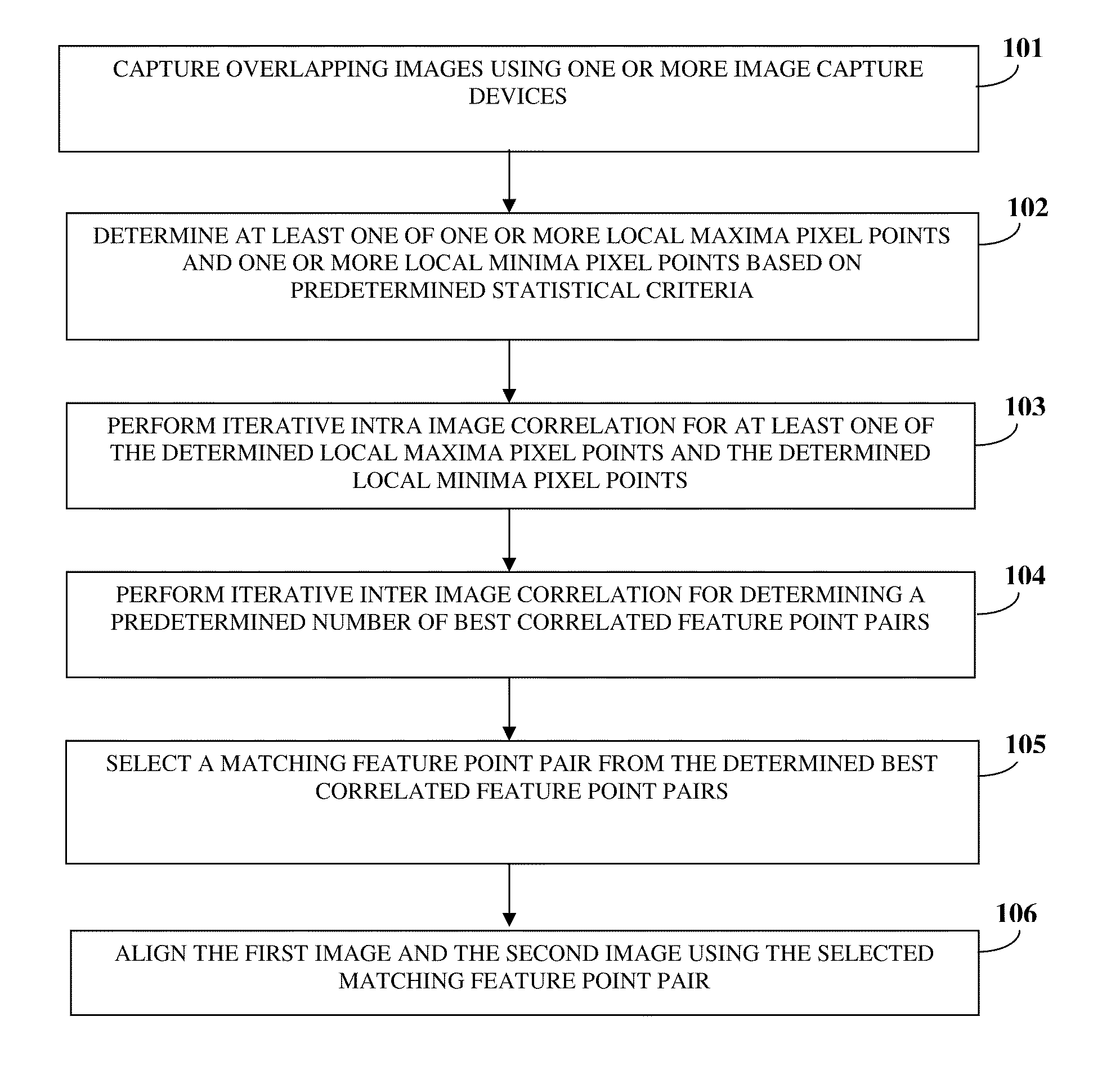
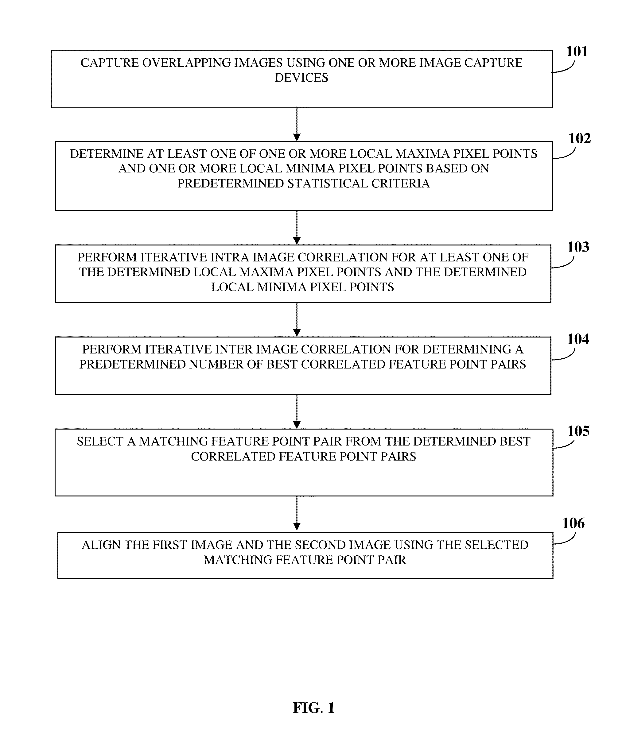
FIG. 1 illustrates a computer implemented method of aligning multiple overlapping images in real time using translation invariant feature matching. Each of the overlapping images overlaps an adjacent image of the overlapping images. A user captures 101 overlapping images comprising, for example, a first image and a second image using one or more image capture devices. For purposes of illustration, the detailed description refers to a first image and a second image; however the scope of the computer implemented method and system disclosed herein is not limited to the first image and the second image but may be extended to include an almost unlimited number of images. In the computer implemented method and system disclosed herein, the first image and the second image are about the same scale. The first image and the second image are, for example, a pair of overlapping images, a pair of images comprising inter image jitter, etc. The image capture devices are, for example, cameras, mobi...


PUM


Abstract

A computer implemented method and system is provided for aligning multiple overlapping images in real time using translation invariant feature matching. A user captures overlapping images comprising a first image and a second image using one or more image capture devices. An image aligning application determines one or more local maxima pixel points and local minima pixel points in the first image and the second image based on predetermined statistical criteria. The image aligning application performs iterative intra image correlation in the first image for selecting a predetermined number of feature points. The image aligning application performs iterative inter image correlation for the selected feature points, for determining a predetermined number of best correlated feature point pairs, and selects a matching feature point pair from the best correlated feature point pairs. The image aligning application aligns the first image and the second image using the selected matching feature point pair.

Description

CROSS REFERENCE TO RELATED APPLICATIONSThis application claims the benefit of non-provisional patent application number 2541 / CHE / 2009 titled “Image Alignment Using Translation Invariant Feature Matching”, filed on Oct. 21, 2009 in the Indian Patent Office.BACKGROUNDThe computer implemented method and system disclosed herein, in general, relates to image processing. More particularly, the computer implemented method and system disclosed herein relates to aligning multiple overlapping images in real time using translation invariant feature matching.Digital image capture is a well known technique used for capturing images using lower cost optical to electronic conversion devices. Advantages of using a digital image capture device is the ability to capture, store and immediately view an image, and the ability to correct defects in the saved image either in situ or later using a computer system. However, to cover wide space, large field view lenses are used resulting in barrel distortion...

Claims


Application Information

Patent Timeline
Patent Type & Authority Applications(United States)
IPC IPC(8): G06K9/32G06K9/36G06K9/64G06K9/40
CPCG06K9/4671G06K2009/2045G06T3/4038G06T2207/10016G06T7/0034G06T2200/32G06T7/003G06T7/337G06T7/35G06V10/16G06V10/462
Inventor CHANDRASHEKAR, PUNEETH BILAGUNDASANGAPPA, HEMANTH KUMARKUMARASWAMY, SURESH KIRTHI
Owner LTIMINDTREE LTD
Why Eureka
Try Eureka