
Orthodontic appliance

Active Publication Date: 2011-04-21
FARRELL CHRISTOPHER JOHN
View PDF27 Cites 34 Cited by
  • Summary
  • Abstract
  • Description
  • Claims
  • Application Information

AI Technical Summary

Benefits of technology

[0029]The appliance may have a flexibility that permits the appliance to be manually flexed or deformed out of the resting form to fit the underdeveloped dental arch into the dental arch receiving channel.
[0078]The one and further cutaways enable the teeth engaging member provide space when the left and arm regions of the appliance are moved towards each other when the appliance is manually flexed out of its resting form.
[0082]This encourages relaxation of the muscles, particularly where the user has a malocclusion and there is a space between the occlusal surfaces of the dentition on the upper and lower arches. It also supports the temporomandibular joint (TMJ joint).
[0084]According to another aspect of this invention there is provided an orthodontic appliance for promoting development of a dental arch form in a patient who has an underdeveloped arch form, the appliance including:a base member that is made of a resiliently flexible material having a shape that corresponds generally to a dental arch form, and a teeth engaging member that encloses at least part of the base member and that defines at least one of upper and lower dental arch receiving channels, the teeth engaging member being made of a resiliently flexible material that is more flexible than the resiliently flexible material of the base member and that can be deformed,wherein the appliance comprises a front region and left and right arm regions on either side of the front region, and the front region is formed with a greater stiffness than the left and right arm regions, and the appliance has a resting form in which the resilient materials of the base member and the teeth engaging member are in their resting condition, and when the appliance is deformed out of the resting form to fit the underdeveloped dental arch form into the dental arch receiving channel, the greater stiffness of the front region enables it to exert a greater return force against an anterior region of the dental arch form than the arm regions bearing against other regions of the dental arch form.
[0093]The method may include encouraging development of the upper arch of a patient by expanding the upper arch form to treat a Class 2 malocclusion.

Problems solved by technology

A limitation of plate appliances is that the cost of producing them is high because they are individually made for each patient in a dental laboratory based on a dental model of the patient and a bite impression of the patient.
The brackets of the braces are generally unsightly and detract from the patient's looks while the braces are being worn, e.g. for the direction of the treatment.
Secondly the braces can be uncomfortable to wear and can cause trauma, such as cuts and bruises to the intraoral soft tissues of a user.
The soft buccal mucosa is particularly susceptible to injury from projections on the buccal surface of the brackets.
Thirdly the brackets and wire are permanently attached to the dentition and thus cannot be temporarily removed by a patient in the way that a removable appliance can be removed.
If the braces are particularly uncomfortable at any point in time to a user they cannot be temporarily removed to afford the patient some respite from the discomfort.
Fourthly another problem that has plagued the use of braces is patient relapse.
They cannot be used on an intermittent basis to provide a retaining function after the braces have been removed in the way that a removable appliance can be used.
The braces do not offer a realistic or practical option as a retainer appliance once its use as an active appliance to achieve teeth repositioning is completed.
However because the appliance material is soft and flexible it does not exert a resilient force that is strong enough to significantly develop the bone structure of the dental arch of the user.
In addition such an appliance does not make a significant contribution to alignment of the dentition on the associated arch.

Method used


Image

  • Orthodontic appliance
  • Orthodontic appliance
  • Orthodontic appliance

Examples


Embodiment Construction

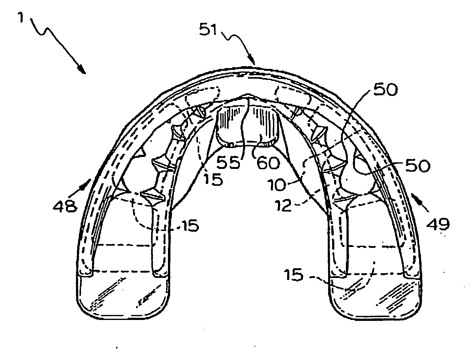
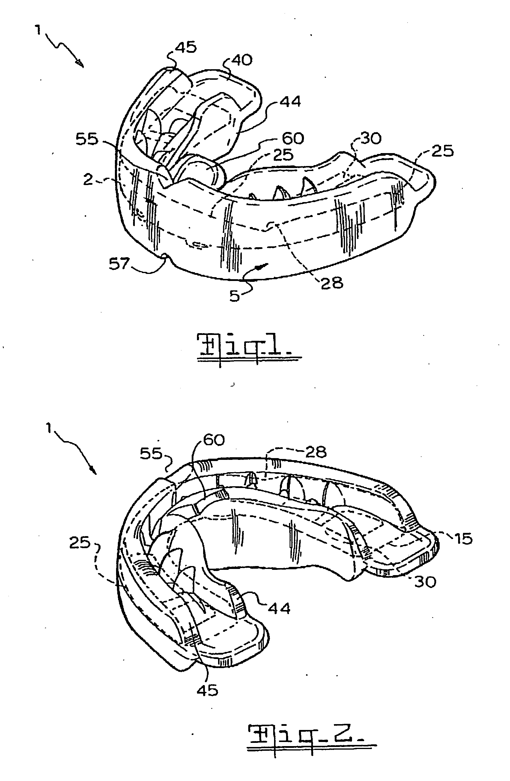
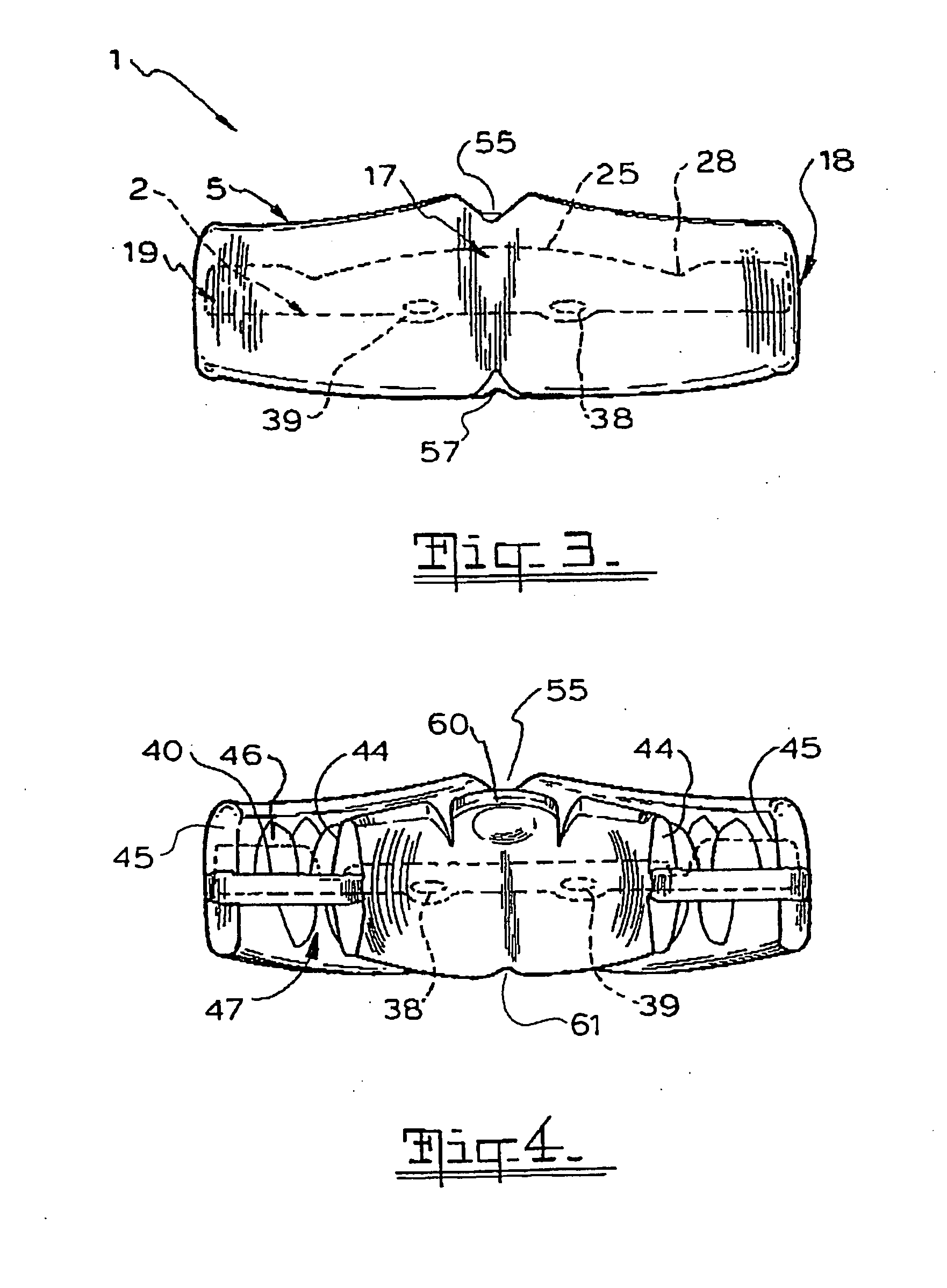
[0096]An orthodontic appliance in accordance with this invention may manifest itself in a variety of forms. It will be convenient to hereinafter provide a detailed description of at least one embodiment of the invention with reference to the accompanying drawings. The purpose of providing this detailed description is to instruct persons having an interest in the subject matter of the invention how to put the invention into practice. It is to be clearly understood however that the specific nature of this detailed description does not supersede the generality of the preceding statements. In the drawings:

[0097]FIG. 1 is an upper three dimensional view of an orthodontic appliance that is an orthodontic appliance in accordance with one embodiment of the invention, viewed from the front;

[0098]FIG. 2 is an upper rear three dimensional view of the appliance of FIG. 1, viewed from the rear;

[0099]FIG. 3 is a front view of the appliance of FIG. 1;

[0100]FIG. 4 is a rear view of the appliance of...


PUM


Abstract

An orthodontic appliance 1 for promoting development of a dental arch form in a patient who has an underdeveloped dental arch form is disclosed. The appliance 1 includes an arch-shaped base member 2 that is made of a resiliently flexible material, and a teeth engaging member 5 that encloses at least part of the base member 2. The teeth engaging member 5 defines upper and / or lower dental arch receiving channels 46, 47 and is made of a resiliently flexible material that is softer than the base member and is deformable. The appliance 1 has a resting form in which the resilient materials of the base member 2 and the teeth engaging member 5 are in their resting condition. The appliance 1 can be flexed or deformed out of the resting form to fit the underdeveloped dental arch form into the dental arch receiving channel 46, 47. When deformed the appliance 1 exerts a return force that is directed to returning it to its resting form which in use urges the underdeveloped dental arch to expand into a developed dental arch form.

Description

[0001]This patent is a continuation-in-part of U.S. application Ser. No. 11 / 787,661, filed 16 Apr. 2007, now abandoned, which was a continuation-in-part of PCT / AU05 / 01598, filed on 14 Oct. 2005, which designated the United States, now lapsed, which claimed priority to AU 2004 905924 filed on 14 Oct. 2004.FIELD OF THE INVENTION[0002]This invention relates to an orthodontic appliance for use in orthodontic treatment for developing an underdeveloped arch into a developed arch form.[0003]This invention relates particularly but not exclusively to an orthodontic appliance for use in treating a Class 2 malocclusion by promoting expansion of an underdeveloped upper dental arch. It will therefore be convenient to hereinafter describe the invention with reference to this example application. However it is to be clearly understood that the invention is capable of broader application. For example it can find application in orthodontic treatments other than those seeking to expand the patient's ...

Claims


Application Information

Patent Timeline
IPC IPC(8): A61C7/08
CPCA61F5/566A61C7/08A61J17/02
Inventor FARRELL, CHRISTOPHER JOHN
Owner FARRELL CHRISTOPHER JOHN
Learn More